| Radio Antenna Engineering is a free introductory textbook on radio antennas and their applications. See the editorial for more information.... |

|
Home  Low-Frequency Antennas Directive Antennas Wave Antenna Low-Frequency Antennas Directive Antennas Wave Antenna |
||||||||||||


|
  |
|||||||||||
|
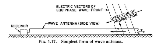
Wave AntennaAuthor: Edmund A. Laport The wave, or Beverage, antenna has for many years been the principal low-frequency directive antenna for the fixed services, especially for frequencies below 100 kilocycles. It was apparently the first antenna to be developed using the traveling-wave principle. Since 1920, this principle has been applied to many other forms of antennas for frequencies over the entire present-day range of radio frequencies.
The simplest form consists of a single wire terminated in its characteristic impedance to ground at the end nearest to the sending station. The other end terminates in the receiver. This type of antenna is responsive to vertically polarized waves by virtue of the fact that the electric vectors of a wavefront, when passing over the imperfectly conducting earth, are tilted forward in the direction of propagation. This produces a component of electric force that is parallel to the wire and induces a current in it. This current flows in the direction of wave travel, which is toward the receiver end of the wave antenna. All portions of the antenna collect additional energy from the impinging wavefront in space, and the energy extracted from the passing wave field is cumulative so long as the phase of the wave in the antenna does not become greatly different from that of the exciting field. The length of the wave antenna can be increased to advantage up to the point where destructive interference begins to take place between the wave field and the wire field. Where this cumulative effect reaches its optimum value depends upon the conductivity of the soil surrounding the antenna, the frequency of the incoming wave, and the orientation of the antenna with respect to the direction of wave travel in cases where the antenna is not oriented in that direction. This latter condition is responsible for the wave antenna's pronounced directivity pattern, together with the condition of far-end termination, which dissipates all energy traveling in the opposite direction in the antenna. These effects are characteristic of all traveling-wave antennas. The best location for a wave antenna is where the soil conductivity is lowest to a considerable depth (preferably as deep as the skin thickness). Unlike most other site requirements where the highest possible soil conductivity is desired, in the low-frequency wave antenna low conductivity is desired to obtain maximum wave tilt and the maximum exposure of the wire to the tilted wave field.
The characteristic impedance of the wave antenna is that of an unbalanced transmission line. It can be computed from the cross-sectional geometry of the antenna. One or more wires may be used to obtain characteristic impedances between 300 and 500 ohms. Single-wire wave antennas will suffice for many applications. It is often desired to reverse the direction of maximum response in order to receive stations from two reciprocal directions at different times, or perhaps simultaneously. There are situations where it is more convenient to locate the receiving equipment near the blind end. These requirements are easily met by using a wave antenna consisting of two parallel wires as shown in Fig. 1.18A. The wave field impinges upon these two wires simultaneously, and equal currents are caused to flow in both wires in the direction of wave travel. These currents continue to flow until they reach the far end of the antenna, where a reflection transformer is used to transform the collected current from unbalanced to balanced form. The energy thus transformed is then propagated backward along the antenna to the receiver. In this case, the receiver is connected between the two wires instead of from the wires to ground. The input impedance of the receiver is made equal to the impedance of the two wires functioning as a transmission line. To suppress pickup from the opposite direction, the neutral point of the balanced input circuit is connected to ground through a resistance equal to the characteristic impedance of the two wires to ground. The reflection transformer shown in Fig. 1.18A is an inductive transformer having a ratio of Z01 unbalanced to Z02 balanced, and connected as shown. Z01 designates the characteristic impedance of the two wires unbalanced to ground, and Z02 is the balanced characteristic impedance between wires. In this diagram, reception is intended from one direction only, using one receiver. In Fig. 1.18B, two receivers are used for simultaneous reception from two reciprocal directions. The input to one receiver is matched to Z02 balanced and the other to Z01 unbalanced and connected as shown. In this diagram, reflection from the far end is accomplished by grounding one wire and leaving the other open-circuited.
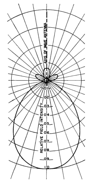
This balances the current received from the right but has no effect on the unbalanced current received from the left. In order to obtain sufficiently correct balances in the transformers, an electrostatic shield is indicated. The characteristic impedance Z01 is in general a function of frequency, varying from the value computed from standard formulas which assume a perfectly conducting earth. It is desirable to measure the characteristic impedance of a system at the working frequencies after erection. This involves special techniques in view of the uncertainties of the ground terminals. Directivity of Wave Antennas. The approximate polar pattern in the horizontal plane for a wave antenna having a length of one wavelength (360 degrees) is shown in Fig. 1.19. A pattern of this type is somewhat dependent upon the underlying soil at a given frequency because of its effect upon the propagation velocity within the antenna system. Additional directivity can be obtained by combining two or more wave antennas in an array. The array can be lateral or longitudinal or a combination of both. Ordinary transmission lines are used to guide the received energy from the antennas to the receivers, and differences in the phases and amplitudes of the different signals, due to inequalities in the transmission-line lengths, are corrected by means of appropriate phasing networks and attenuators at the combining points.
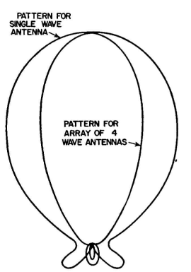
The combining technique may employ either active or passive means in such a way as to avoid interaction between the several antennas. Figure 1.21 shows the circuitry employed for the low-frequency transatlantic-telephone wave-antenna system at Houlton, Maine. Four wave antennas, each 320 degrees long, are arranged in two pairs and are all parallel. Antennas A and B form the first pair, spaced laterally 25 degrees and longitudinally 78 degrees.
A second identical pair, composed of antennas C and D, are spaced laterally 220 degrees. The array therefore utilizes both lateral and longitudinal effects to obtain improved directivity, and the over-all pattern for the array is shown in Fig. 1.20. The wave antenna has the property of substantial aperiodicity and therefore is especially desirable in wide-band systems.
|
||||||||||||
| Home Low-Frequency Antennas Directive Antennas Wave Antenna |
|
|||||||||||


Last Update: 2011-03-19