| Radio Antenna Engineering is a free introductory textbook on radio antennas and their applications. See the editorial for more information.... |

|
Home  Low-Frequency Antennas Directive Antennas Adcock Antenna Low-Frequency Antennas Directive Antennas Adcock Antenna |
||||||||||||||||


|
  |
|||||||||||||||
|
Adcock AntennaAuthor: Edmund A. Laport Another principle for low-frequency directive transmission and reception is used in the Adcock antenna.
This antenna basically consists of two spaced vertical radiators with their currents in (or very near) phase opposition. Such a pair of radiators has substantially the characteristics of a loop antenna, but with the additional property that the feeders between the two radiators are made nonradiating. (They are often in the form of buried coaxial feeders.)
The merit of this system of navigation is that an ordinary receiver is used in the aircraft. When equal signals are obtained from both the A and the N sides of the radio-range system, a steady signal is heard by the pilot and he is on one of the four courses. The apparent width of a course is of the order of 3 degrees. Outside of this zone, the difference in signal level is apparent, and the A or the N signal can be distinguished to indicate which side of the course the aircraft is on. This is indicated in Fig. 1.24, which shows the transition of the signal from a pure N to a pure A and passing one equisignal (on-course) bearing. Feeding A-N Arrays. The two Adcock pairs in this system are fed through a cross-coil goniometer having two primaries and two secondaries. The A signals are fed across one primary and the N signals across the other. One secondary excites the first pair of diagonal radiators and the other the second pair.
The goniometer is designed to be rotatable, so that when in other than the zero position the currents of the two pairs are actually distributed among the four radiators. The field pattern rotates with the goniometer rotation. The goniometer position is therefore a factor in the resulting pattern, when in other than the zero position, and plays a part in the bending of the courses to prescribed azimuths. The installation, adjustment, and calibration of a four-course radio range of this type (by flight checks) may require that only two of the courses be aligned to specified azimuths, in which case the others may fall at random. In other cases three or all four of the courses may have to be oriented at specified azimuths. Out of the great variety of possible combinations, Figs. 1.25 to 1.28 are included to show the effects of the goniometer position and the effects of feeder line lengths in adjusting the phase differences in one or both pairs of radiators.
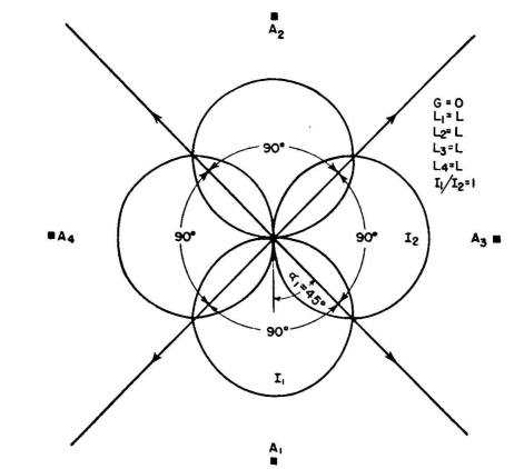
In these diagrams the locations of the four radiators are shown. Each legend gives the goniometer position in degrees from reference position, G, the differential in the electrical lengths L1 and L2 of feeders to the radiators A1 and A2, and the differential in the electrical lengths L3 and L4 to radiators A3 and A4.
Each feeder to each tower includes a straight run of coaxial feeder and an adjustable artificial-line network which builds out the electrical length of each feeder until it is equivalent to 90 degrees, approximately, from the goniometer. Therefore there is a total of about 180 degrees in the feeding system between a pair of radiators in the reference optimum initial condition, To produce phase differences between the currents of
a pair, this total feeder length is held constant, and the goniometer is, in effect, moved off the center of the feeder, by removing, say, 4 degrees of length from the artificial-line network on one side and adding the same amount on the other side. The same is done independently in the feeding of both Adcock pairs. Figure 1.22 shows the perfectly symmetrical pattern with reciprocal 90-degree courses when the goniometer is in its zero position and the currents of each pair are identical and exactly antiphased. ´
Figure 1.23 is the same except that now an attenuator has been introduced in the feeder to the first pair to decrease the currents in that pair with respect to the currents in the second pair. This retains the same pattern shape for the first pair, but its amplitude is reduced. At the same time it squeezes the courses as shown but retains their reciprocal relationship. In Fig. 1.25, the goniometer remains at zero. The currents of the first pair are in exact antiphased relationship, but the currents of the second pair are now 16 degrees out of antiphased relation. As a result, one pair of courses is squeezed, and the opposite pair is expanded. The two reciprocal intermediate angles remain at 90 degrees. The symmetrical figure-of-eight pattern of the first pair is combined with the asymmetrical figure-of-eight pattern of the second pair. In Fig. 1.26 both pairs have the asymmetrical figure-of-eight pattern due to a phase difference of 12 degrees from antiphase condition. It can be seen that the angle between adjacent courses is the same on opposite sides of the whole pattern. The goniometer remains in the zero position. Figure 1.27 is the same as Fig. 1.22 except that a 30-degree rotation of the goniometer has rotated the pattern 15 degrees.
Figure 1.28 shows equal 20-degree phase deviations from antiphase for both pairs, but the goniometer is now set at 75 degrees. The patterns from the two pairs are seen to be unequal, and the angles between courses are all different. In all the above cases except Fig. 1.23 the currents in the two pairs have been the same. In this case the ratio was changed by connecting an attenuator in the feeder to one pair. The adjustment of this current ratio between pairs, the setting of the goniometer, and the phasing of the two pairs provide the means for obtaining the very great range of course settings used in practice. The use of approximately one-half wavelength of feeder between the radiators of a pair, consisting of coaxial line and artificial building-out networks having the same characteristic impedance, gives the maximum intrinsic stability of the system in the presence of radiator impedance variations due to weather and other influences. When it is recalled that the radiators are electrically short and have low resistance and high reactance at the frequencies between 200 and 400 kilocycles, it can be expected that variations that might ordinarily be negligible can readily become important in such a phase- and amplitude-sensitive system. The special properties of the half-wavelength line are employed to maintain a high degree of stability with the impedance variations inevitably encountered in service.
In the design and installation of the radiators and the ground systems every effort is made to minimize impedance variations due to changes in soil characteristics, the movement of the radiators in the wind, the presence of moisture films and water on the insulators at the base and the feed bushings, and many other effects which are of lesser importance but which cumulatively can be disturbing. Other variations are imposed by the cooling and heating of the tuning inductances due to power dissipation and to solar radiation and weather conditions throughout the seasons. The radio range is also used for the transmission of voice signals for instructions and information to pilots. In the nonsimultaneous type using only the four radiators previously discussed, all four radiators are excited in phase when the voice signals are transmitted. This involves switching from the four course navigational form of system excitation to parallel excitation for omnidirectional transmission, and the navigational facilities are absent during the voice transmission. A later form of radiating system, known as the "simultaneous" radio range, places a fifth radiator at the center of the array, and voice signals can be transmitted from this central radiator without interrupting the navigational signals. In the receiver, the 1,020-cycle tone modulation used for navigation is selected by a filter to provide the navigational signals, while the voice circuit filters out this tone so that it will not interfere with the reception of voice signals. One receiver equipped with this reciprocal filter system provides the two types of signals in two output circuits simultaneously. The cross-Adcock antenna system has also been used for fixed direction-finding stations for low- and high-frequency applications.
|
||||||||||||||||
| Home Low-Frequency Antennas Directive Antennas Adcock Antenna |
|
|||||||||||||||


Last Update: 2011-03-19