| Radio Antenna Engineering is a free introductory textbook on radio antennas and their applications. See the editorial for more information.... |

|
Home  Medium-frequency Broadcast Antennas Radiation Characteristics of a Vertical Radiator The Folded Unipole Medium-frequency Broadcast Antennas Radiation Characteristics of a Vertical Radiator The Folded Unipole |
||||||


|
  |
|||||
|
The Folded UnipoleAuthor: Edmund A. Laport
Let R0 represent the base resistance of the radiating system operating as a simple series-fed antenna, and let /o represent the total base antenna current when the system has a power input of W watts. When excited as a folded unipole, the total antenna current for the same power input will be I0 as before, except that, with one conductor grounded and the other fed by the transmitter, the latter carries only a portion M of the total current. Then, if R1 designates the input resistance when excited as a folded unipole,
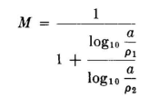
The value of M will differ with the relative radii of the two conductors and will be 0.5 when the two conductors are identical, so that the total antenna current is equally divided between the two. However, when one conductor is a grounded quarter-wave tower and the other is a wire, the great disparity in radii will cause the value of M to be very much less than 0.5. If the tower and the "drop" wire were both continuous uniform-section cylindrical conductors, the value of M could be obtained from the relation where ρ1 is the radius of the larger conductor, ρ2 the radius of the smaller conductor, and a the axial separation between the two.
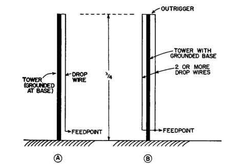
However, if a steel tower that is not cylindrical is the larger conductor, an approximate value of M can be found by supposing the tower to be equivalent to a cylinder with the same sectional periphery. A large tower and a small drop wire, as shown in Fig. 2.13A, will often yield rather small values of M. If one wishes to raise the value of M, two or more drop wires may be used, all insulated from the tower throughout their length except at the top and connected together at the bottom, where they are fed, as shown in Fig. 2.13B. Thus the transformation ratio of the drop wire can be varied more or less at will to bring a pre-desired value of resistance at the feed point. This may be a value of resistance that will directly match a given feeder characteristic impedance. This method is best adapted to quarter-wave uniform-section radiators which are self-resonant by virtue of their height. Tapered towers can be made to be substantially of uniform section by using other drop wires suspended from a spreader at the top having the same width as the tower base and connecting these wires to the tower proper. Then the additional drop wires for forming the unipole are affixed where they will not interfere with the former. Figure 2.14 shows a plan view of a tapered square radiator using drop wires for feeding and to equalize the tower cross section.
A folded unipole of this type allows all of the conveniences afforded by the use of directly grounded towers without compromising the natural current distribution or introducing pattern distortion from a sloping wire. The input impedance can be made almost purely resistive with a value that will directly match open-wire feeders of common types, designed for the proper characteristic impedance.
|
||||||
| Home Medium-frequency Broadcast Antennas Radiation Characteristics of a Vertical Radiator The Folded Unipole |
|
|||||


Last Update: 2011-03-19