| Radio Antenna Engineering is a free introductory textbook on radio antennas and their applications. See the editorial for more information.... |

|
Home  Medium-frequency Broadcast Antennas Uniform-cross-section Vertical Radiators Medium-frequency Broadcast Antennas Uniform-cross-section Vertical Radiators |
||||||


|
  |
|||||
|
Impedance of Uniform-cross-section Vertical RadiatorsAuthor: Edmund A. Laport
A continuous cylindrical vertical radiator of perfect conductivity, with its lower end very near to a perfectly conducting flat earth plane, has a resistance and a reactance that may be computed from published formulas.
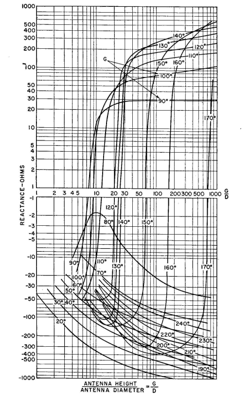
The values can be read with adequate accuracy for most purposes ( It is apparent from the foregoing that one must be content with approximate estimated values of radiator impedance values during preliminary design, leaving for the final stage the measurements to be made after erection. Typical coupling networks for energizing the system have sufficient adjustability so that they will accommodate any ordinary discrepancies between the preliminary estimated values and the final working values. When two or more radiators are to be employed in a directive array, the estimated impedances must be derived with care if the feeding networks are to be precalculated with acceptable accuracy. An example of the use of the intrinsic impedance data to estimate the input impedance to a vertical radiator under actual working conditions is the following: A vertical radiator of height G = 125 degrees at a frequency of 600 kilocycles will have a square cross section 10 feet per side. The base insulator to be used has a capacitance of 60 micromicrofarads. A tower-lighting transformer and spark gap will add another estimated 75 micromicrofarads in parallel with the base insulator. No other attachments are needed. What will input impedance be at 600 kilocycles? The periphery of the antenna should be equivalent to a cylinder having a diameter of about 12 feet. At 600 kilocycles this diameter expressed in electrical degrees is 2.63. The ratio G/D = 47.6. For this form factor and height 125 degrees, Fig. 2.15 shows a resistance of about 240 ohms, and Fig. 2.16 shows a reactance of about j185 ohms. These are the components of the intrinsic impedance of the antenna without any spurious influences. If now the effect of the capacitance of 135 micro-microfarads added across the base of the radiator is computed, it is found that the input impedance to the system will then be
When tower-lighting power is fed through an isolating inductor, an inductive reactance may then appear across the base insulator, which neutralizes a portion of the base-insulator capacitive reactance. In addition, the resistance of such an inductor parallels the antenna resistance, owing to its finite dissipation factor Q. If this inductor is self-resonant at the working frequency, its presence modifies only the resistance. If its resonant frequency is lower than the working frequency, it will act as a shunt capacitance. In some instances the reactance of the isolation inductor can be made equal to that of the base insulator and of sufficiently high Q so that the input impedance to the system is very nearly equal to the intrinsic antenna impedance. The transformed impedances of vertical radiators are of special interest in directive arrays where the design of the entire system must proceed on computed values of impedances and networks. This is because it is physically impractical to measure the desired impedances until the array is functioning correctly. It must be remembered that the theoretical values of mutual impedance are also intrinsic values. The input impedance to each radiator in an array is computed first with intrinsic values of self- and mutual impedances. These different impedances are then transformed to true accessible impedances through the masking impedances of the various attachments, base insulator, etc. It is in such cases that one may desire to design light-feed isolation inductors to neutralize the reactance of the base insulator so that intrinsic and observed impedances will be in accord.
|
||||||
| Home Medium-frequency Broadcast Antennas Uniform-cross-section Vertical Radiators |
|
|||||


Last Update: 2011-03-19