| Radio Antenna Engineering is a free introductory textbook on radio antennas and their applications. See the editorial for more information.... |

|
Home  Medium-frequency Broadcast Antennas Input Impedance in a Directive Array Feeder System for a Three-radiator Array Medium-frequency Broadcast Antennas Input Impedance in a Directive Array Feeder System for a Three-radiator Array |
||||||||||||||||||||||||||||||||||||||


|
  |
|||||||||||||||||||||||||||||||||||||
|
Feeder System for a Three-radiator ArrayAuthor: Edmund A. Laport
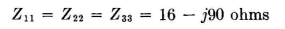
At the working frequency the self-impedances
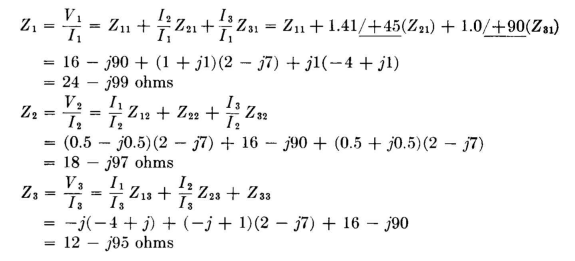
From symmetry, it is evident that and
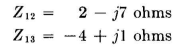
From Appendix III, Fig. D, the following values are read
The input impedance to each radiator is then computed.
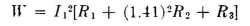
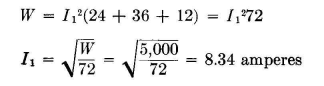
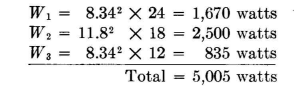
The power input to the system is
but using the current ratios,
By arithmetic, after substituting the resistances,
Then
Now that all the input-impedance information has been determined, decisions can be made regarding the feeder system. It is noted that half of the total power is in radiator 2.
It will probably be well to bring the main transmission line up to this radiator and use the simplest possible network - a simple two-element L circuit. Then power to the two outer feeders can be fed each way from the middle, with lines running between the radiators. The block diagram of Fig. 2.24 illustrates the problem. Network A will couple radiator 2 to the main feeder. Network B will divide power and take enough from the main feeder to excite radiator 1, and network C will do the same for radiator 3. Network D will terminate the line on the left and couple into radiator 1, and network E will do the same for the right-hand line. Networks A, B, and C in parallel will match the main feeder. Choosing a convenient open-wire line of characteristic impedance such as 200 ohms, the potential on the main line will be
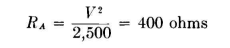
For 2,500 watts into network A, its input resistance must be
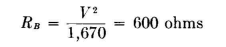
For 1,670 watts into network B, its input resistance must be
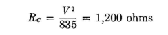
For 835 watts into network (7, its input resistance must be
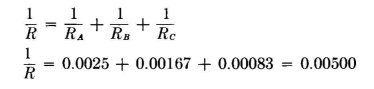
Networks A, B, and C in parallel give a resistance value of from which R - 200 ohms.
At this point the impedance-matching requirements are known for each network, as follows:
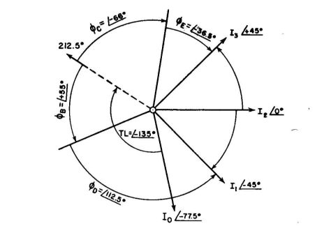
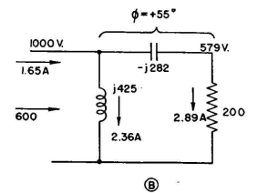
The required phase shift in each network must now be determined. This phase shift pertains to the currents of the system. The phase length of the terminated lines between radiators is the same as their electrical length of 135 degrees - the spacings between radiators. Using an L network at A makes us dependent upon the phase shift that happens to come out of the imposed conditions, because with an L network there is no independent control of phase shift. Hence before going further this network will be solved. The result is shown in Fig. 2.26, and the phase shift is +77.5 degrees. The total phase lag between the currents of radiators 2 and 1 must be 45 degrees. From the main line to radiator 2 there is a phase advance of 77.5 degrees. From the main line to radiator 1 there must therefore be a total phase advance of 77.5 - 45 = 32.5 degrees. There is already a phase lag of 135 degrees in the line, so that there must be a phase advance of 135 + 32.5 = 167.5 degrees introduced by networks B and D. The choice of networks is arbitrary, but advantage can be taken of simpler circuits if one of these networks is an L, using only two elements. If B is so made, we tie down its phase shift. Upon solution of the circuit of Fig. 2.27 we find the phase shift to be +55 degrees. This leaves
+ 112.5 degrees to be obtained in network D, which is obtained by the circuit of Fig. 2.29. Network C can be made in the form of an L also because the phase remainder can be taken up in E. The total phase shift between the main feeder and radiator 3 must be -237.5 degrees, of which there is -135 degrees in the line. Between networks C and E there must be a total phase shift of -237.5 + (-135) = 102.5 degrees.
|
||||||||||||||||||||||||||||||||||||||
| Home Medium-frequency Broadcast Antennas Input Impedance in a Directive Array Feeder System for a Three-radiator Array |
|
|||||||||||||||||||||||||||||||||||||


Last Update: 2011-03-19