| Radio Antenna Engineering is a free introductory textbook on radio antennas and their applications. See the editorial for more information.... |

|
Home  Medium-frequency Broadcast Antennas Input Impedance in a Directive Array Feeder Circuits for Directive Arrays Medium-frequency Broadcast Antennas Input Impedance in a Directive Array Feeder Circuits for Directive Arrays |
||||


|
  |
|||
|
Feeder Circuits For Directive ArraysAuthor: Edmund A. Laport When the working input impedance to each radiator in an array is known, the next step in design is to compute the networks of the feeder system. The design starts with a consideration of the arrangement of transmission lines, of which there may be several choices from a cost standpoint. For example, one may choose to run a separate transmission line from each radiator to the transmitter and join these feeders together in a network near the transmitter. Or it may be decided to run one line from the transmitter to one of the radiators and go on from there to the others in succession, with coupling and power-dividing networks at each radiator along the line to the last. Or there may be combinations of these two basic methods. Then there is the choice of matching each line at each point in its characteristic impedance or allowing certain standing waves to exist, with the consequent transformation of impedance by the unmatched lines. Here again the choice is one of economy in engineering time and materials if the mismatches are not large.
The easiest system to design is one using separate lines from each radiator to the transmitter, each line being correctly matched in its characteristic impedance. If perchance the power input to each radiator is the same and the lines have the same characteristic impedance, they can all be connected directly in parallel near the transmitter. The phasing of the different radiator currents is accomplished in each radiator by the combination of the electrical length of each line and the phase difference effected by its impedance-matching network at the radiator.
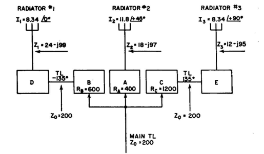
In the case of successive feeding, the full transmitter power is fed into a common line to the first radiator. Here one network extracts the proper power for that radiator through a coupling network with a predetermined phase shift, positive or negative. The remainder of the power is fed through the line to the next radiator, where again a portion is taken out for the second radiator and the rest sent on, etc. The last radiator has simply a coupling network, from which it receives the remaining power that it requires. The phase shifts, as well as the proper impedance matches, are built into each network along the system. Allowance is made for losses and attenuation in the lines also. It is helpful to start the design of the feeder system by making a block diagram showing every network and every section of line, with points of paralleling included. If matched lines are to be used everywhere, as is usually preferred by engineers, the phase lag for each section of line is immediately known from its length and is so marked in the diagram. Specified phase shifts are then assigned to the different networks of the system, making arbitrary divisions between two or three networks that may occur in one branch so long as the total phase shift is correct. When all the phases have been assigned, the diagram can be marked with input and output impedances for each block. Power dividing is usually done by paralleling networks, using different resistance values to effect the power division when energized with a common potential. The input resistance to the paralleled networks is made that which will terminate the transmission line. When the block diagram is completed with the terminal impedances and phase shift of each block shown, the synthesis of each network then proceeds in a routine manner. The electrical design is followed by the design of the reactive components and then by the mechanical assembly of each network. In low-power systems it is often feasible to house the networks of small components in weatherproof boxes located near each radiator. When this becomes impractical because of size, a cabin is made to house the equipment. Since all vertical radiators for medium-frequency broadcasting have ground as one side of the circuit, it is desirable to employ unbalanced transmission lines in the feeder system. It is a needless complication to employ balanced lines in such cases and thus have to make balanced-to-unbalanced conversions in the circuits.
|
||||
| Home Medium-frequency Broadcast Antennas Input Impedance in a Directive Array Feeder Circuits for Directive Arrays |
|
|||
Last Update: 2011-03-19