| Radio Antenna Engineering is a free introductory textbook on radio antennas and their applications. See the editorial for more information.... |

|
Home  Medium-frequency Broadcast Antennas Vertical Radiator for Two Frequencies Medium-frequency Broadcast Antennas Vertical Radiator for Two Frequencies |
||||


|
  |
|||
|
A Single Vertical Radiator for Two Different FrequenciesAuthor: Edmund A. Laport
One radiator can be used to transmit two different frequencies simultaneously provided that the frequencies are not too close together and that the radiation characteristics at the two frequencies are satisfactory.
Feeders from each transmitter are brought to a common junction through networks that are designed to provide the proper impedance match at one frequency and simultaneously to act as a stopper circuit for the other frequency. This prevents energy from one transmitter finding its way into the output circuits of the other transmitter, where it would cause cross talk between the two programs.
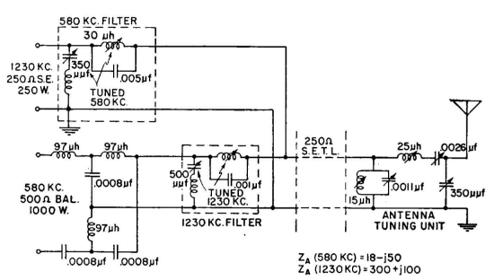
Using complementary stopper circuits in each feeder near their common junction provides the requisite unidirectional power flow from each transmitter into the common circuit and thence to the antenna. At the antenna, the coupling network must match the antenna impedance to the feeder at the two frequencies, taking into account the fact that the antenna impedance will be different at each of the frequencies. Furthermore, all this must be done without impairing the bandwidth requirements for each transmitter. The solution of such a problem depends entirely upon the conditions prevailing and perhaps upon the ingenuity of the designing engineer. The problem gets more serious as the two frequencies get closer together. In general it can be said that the frequencies should differ by 100 kilocycles or more in the medium-frequency broadcast band, but at least one case is known where the frequency difference was less than this. It may be instructive to describe the circuits for one such problem, in which a broadcast transmitter having a 500-ohm balanced output and working on 580 kilocycles was to be used in parallel with another transmitter of 250 ohms unbalanced output on 1,230 kilocycles. A 250-ohm unbalanced open-wire line was used from the antenna to the radio station, and so it was necessary to employ a balance-to-unbalance network, 500/250 ohms, between the 580-kilocycle transmitter and its feeder branch. Figure 2.36 shows the circuits and values computed for the system. When installed, only minor trimming adjustments were needed to obtain the desired parallel performance with a single radiator.
|
||||
| Home Medium-frequency Broadcast Antennas Vertical Radiator for Two Frequencies |
|
|||
Last Update: 2011-03-19