| Radio Antenna Engineering is a free introductory textbook on radio antennas and their applications. See the editorial for more information.... |

|
Home  Medium-frequency Broadcast Antennas Directive Antennas Maximum Gain for Two Radiators Medium-frequency Broadcast Antennas Directive Antennas Maximum Gain for Two Radiators |
||||


|
  |
|||
|
Directive Antenna with Maximum Gain for Two RadiatorsAuthor: Edmund A. Laport
It often occurs that directivity is desired to increase field strength in one direction only. Intuitively one thinks of using a cardioid pattern for this purpose. With a two-radiator cardioid pattern, the maximum field strength is about 1.43 times that for the same power into one radiator. The feed system for such an array is relatively complicated because of the need for dephasing the currents in the two radiators, and this in turn causes unequal powers in them. Therefore, unless the suppression of radiation in the backward direction is also a requirement along with the desire to increase signal in the forward direction, this type of system does not provide the best solution.
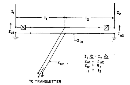
The feeder system for a two-element cophased array with equal currents can be very simple, because the electrical symmetry of impedances and power division permits the system to be energized by a symmetrical feeder system. Figure 2.39 shows the simplest arrangement of a symmetrical feeder system for such an array. The equality of antenna impedances makes it necessary only to apply equal cophased potentials at each radiator base. This can be done by providing identical distances from the transmitter to each radiator.
As illustrated in Fig. 2.39, a main feeder attaches to the center of, a secondary feeder running between the two radiators. These feeders may or may not be matched in their terminal impedances. The admissi-bility of mismatches will depend only on the magnitude of standing waves and the consequent feeder losses. In cases where standing waves on feeders must be avoided the characteristic impedance of the secondary feeder can be made equal to the input resistance of the radiator and identical series reactances used (shown as X) to neutralize any input reactance at the radiators. Otherwise the main feeder, terminated by whatever impedance exists at the middle of the secondary feeder, would in general be mismatched. One can employ a simple L network at this junction to match the main feeder, or one may use a value of characteristic impedance to give an exact or an approximate self-match, together with series neutralization of the existing reactance at the junction. Alternately, the mismatch may be allowed and the input impedance matched to the transmitter with a simple network.
|
||||
| Home Medium-frequency Broadcast Antennas Directive Antennas Maximum Gain for Two Radiators |
|
|||
Last Update: 2011-03-19