| Radio Antenna Engineering is a free introductory textbook on radio antennas and their applications. See the editorial for more information.... |

|
Home  Medium-frequency Broadcast Antennas Directive Antennas Produce a Null at a Specified Angle Medium-frequency Broadcast Antennas Directive Antennas Produce a Null at a Specified Angle |
||||||||||||||||||||||||||||||||||||||||||||||||||||||||||||||||||||||||||||||||||||||||||||||||||||||||||||||||||||||||||||||||||||||||||||


|
  |
|||||||||||||||||||||||||||||||||||||||||||||||||||||||||||||||||||||||||||||||||||||||||||||||||||||||||||||||||||||||||||||||||||||||||||
|
Produce a Null at a Specified AngleAuthor: Edmund A. Laport
For example, a two-element array is to be used to suppress radiation to a prescribed value which is very small (but not necessarily zero) at an angle of 45 degrees in the vertical plane in one direction only. The approach is exactly as though a null at 45 degrees were desired in the horizontal plane also, which is obtained by
There is a range of values of S and φ that will satisfy the problem. The final choice will depend upon the suitability of a particular resulting horizontal pattern. In any in-line array of identical radiators the pattern in the vertical plane through the radiators is obtained by multiplying the horizontal pattern f(β) by the vertical pattern for one of the radiators f0(α). If the array were composed of isotropic radiators, f0(α) would be unity at all angles and so this vertical pattern would be identical to the horizontal pattern. This being so, there will be a null (or minimum) in the vertical pattern at the same angles from the ground as occur in the horizontal pattern, measuring from the line through the radiators. Then, if the vertical pattern f0(α) for the vertical radiator includes one or more nulls of its own, the main vertical pattern under discussion will contain nulls at these vertical angles as well as those derived from the horizontal pattern. To illustrate this, assume that we require a directive-antenna pattern which, among other requirements, must have a null in the vertical plane through the array, in one direction, at 45 degrees.
After some exploratory computations, we have found that an acceptable horizontal pattern is obtained by using two radiators spaced 200 degrees with a phase difference between their currents of 39 degrees. The horizontal pattern for this array is obtained from the following equation:
The relative pattern values from this equation are tabulated in the first column of Table 2.8. There is one null on each side of this pattern at 45 degrees from the line of the radiators. Column 2 of this table is the vertical pattern for a short vertical radiator, short enough so that we can say that its pattern f0(α) = cosα. In using vertical radiators of this type, the main vertical pattern for the array will be the product of column 1 and column 2, which is f(α), tabulated in column 3, with the null at 45 degrees as required. If instead it were desired to employ 190-degree vertical radiators in this array having the vertical pattern f0'(α) listed in column 4, then the main vertical pattern for the array would become that of column 5, which was obtained by multiplying values in column 1 by those in column 4. In this case, there is the null at 45 degrees due to interference between the spaced radiators, and another null at about 65 degrees contributed by the vertical radiator pattern.
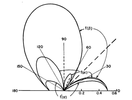
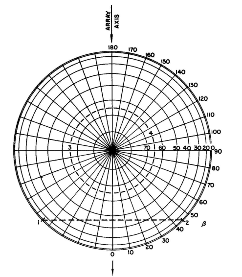
f0(α) = cos a (for short vertical radiators). f'0(α) = [cos (90 cosα) cos (190 sinα)]/sinα (for 190-degree vertical radiator). The patterns for columns 1, 3, and 5 are plotted in Fig. 2.37 for comparison. Note that f'(α) has only a tiny lobe of radiation above 45 degrees so that there is practically no radiation between 45 and 90 degrees on the right-hand side of the diagram. Using the short radiators, there is a rather large high-angle lobe in this space. The admissibility of this lobe would depend upon the problem at hand. Using this same illustration, the locus of all the nulls in the three-dimensional pattern for this array can be found immediately by drawing Fig. 2.38. This is a plane orthographic projection of the hemisphere enclosing the array. The chord line 1-2 is the locus of nulls due to the spacing and phasing of the two radiators and passes through the 45-degree points each side of the array axis where α = 0 (horizontal plane) and also α = 45 degrees in the main vertical plane through β = 0. At other orientations the nulls follow the chord. The null in the vertical plane through β = 30 degrees is seen to be at about 37 degrees above the horizon, and in the direction β = 40 degrees the null occurs at about 24degrees above the horizon.
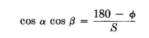
Now consider the dotted circle 3-4 at 65 degrees above the horizon in all directions. This is the null circle for the 190-degree vertical radiator. The only null in the vertical plane for a radiator less than 180 degrees high is at 90 degrees (zenith). This example points the way to a rapid solution for the null angles in the three-dimensional pattern for any linear array of identical vertical radiators. An orthographic projection of the hemisphere is drawn, placing a pole at the zenith and laying out the angles β from the axis of the array from zero to 180 degrees each way. The latitude ( α ) lines are laid out orthographically by drawing circles through points that divide the radius in proportion to cos a, as in Fig. 2.38. With the hemispherical coordinates prepared in this way, place points on the periphery at the angles that correspond to null angles in the horizontal pattern for the array, symmetrically, and draw chords across the chart to connect corresponding nulls on each side of the axis. Then draw circles from the center at any vertical angle for a null in the vertical pattern for the radiator to be used, if there is one. From these the location of the nulls in all other vertical planes can be read directly from the diagram thus prepared. From a diagram of this type one can form a mental picture of the vertical pattern at any azimuth when the horizontal pattern for the array and the vertical pattern for a single radiator are known. It will be recalled that in the direction broadside to the array the vertical pattern for the array will be identical to a single radiator. When the array consists only of two vertical radiators, the null zones in the three-dimensional pattern occur wherever
|
||||||||||||||||||||||||||||||||||||||||||||||||||||||||||||||||||||||||||||||||||||||||||||||||||||||||||||||||||||||||||||||||||||||||||||
| Home Medium-frequency Broadcast Antennas Directive Antennas Produce a Null at a Specified Angle |
|
|||||||||||||||||||||||||||||||||||||||||||||||||||||||||||||||||||||||||||||||||||||||||||||||||||||||||||||||||||||||||||||||||||||||||||


 r
r
Last Update: 2011-03-19