| Radio Antenna Engineering is a free introductory textbook on radio antennas and their applications. See the editorial for more information.... |
|
Home  Medium-frequency Broadcast Antennas Directive Antennas Wide Angles of Suppression Three Radiators Medium-frequency Broadcast Antennas Directive Antennas Wide Angles of Suppression Three Radiators |
|||||||||||||||||||||||||||||||||||||||||||||||||||||||||||||||||||||||||||||||||||||||||||||||||||||||||||||


|
  |
||||||||||||||||||||||||||||||||||||||||||||||||||||||||||||||||||||||||||||||||||||||||||||||||||||||||||||
|
Three RadiatorsAuthor: Edmund A. Laport
from which we compute Table 2.9.
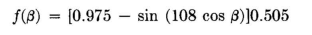
In order to cancel the negative lobe of f1(β) over its angle of constancy we added f2(β) = 0.975, corresponding to a circular source of radiation of relative strength 0.975, located at the center of the pair. The sum of the patterns from the pair and from the central radiator has been calculated and, after normalizing to a maximum relative value of 1.00, tabulated in Table 2.9. The horizontal pattern is plotted in Fig. 2.43. Examination of these values shows that over an angle of +/-50 degrees the field strength is less than 2.5 percent of maximum. Without further calculation it appears that a blind angle of about 102 degrees is possible with this array without exceeding 2.5 percent of maximum field. Furthermore in the vertical plane f( α), using 60-degree radiators, the field does not exceed 6.4 percent of maximum at any angle, and it is below 3 percent at vertical angles up to 50 degrees. If higher radiators are used, the vertical pattern can be reduced much below these values at the higher angles.
The broad beam on the opposite side is constant over the same wide angle. The normalized pattern specification is
For the fields to add in this manner, the central-radiator current must be in quadrature with the currents in the outer radiators. A rectangular plot of the pattern is shown in Fig. 2.43. The current relations will be
The pattern can be inverted by reversing the polarity of the current in the central radiator,
|
|||||||||||||||||||||||||||||||||||||||||||||||||||||||||||||||||||||||||||||||||||||||||||||||||||||||||||||
| Home Medium-frequency Broadcast Antennas Directive Antennas Wide Angles of Suppression Three Radiators |
|
||||||||||||||||||||||||||||||||||||||||||||||||||||||||||||||||||||||||||||||||||||||||||||||||||||||||||||


Last Update: 2011-03-19