|
Structural Details
Author: Edmund A. Laport
The photographs (Figs. 2.51, 2.52 to 2.55, and 2.56 to 2.70) are included to show certain structural details that have been used successfully at a number of broadcast stations. The range of variation in design of structural details is naturally very great, and a few examples can suggest only a few methods that can be used. The figures also show some of the types of radiators in current use - both guyed and self-supporting - together with base and guy-anchor details.
 |
| FIG. 2.56. Base of a self-supporting broadcast radiator during construction. Notice tractor and plow tracks in background where ground wires have been plowed into the soil. (Photograph courtesy of National Broadcasting Company.) |
Since the advent of steel vertical radiators for broadcast applications the radio engineer has been spared the duties of antenna mechanical and structural design. This is now delegated to the tower engineers, who have performed very creditably. Manufacturers of towers are generally familiar with radio requirements and often understand the electrical requirements as well as the structural.
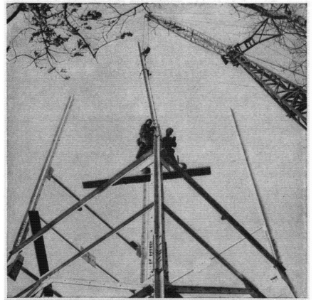 |
| FIG. 2.57. A self-supporting broadcast radiator during construction. |
 |
| FIG. 2.58. Anchor for guy cables for two levels, used with a guyed broadcast vertic radiator, (Photograph courtesy of National Broadcasting Company.) |
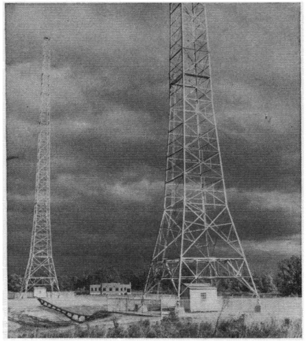 |
| FIG. 2.59. Two self-supporting towers used in a two-element directive array at Radio Station WNBC, Port Washington, New York. (Photograph courtesy of National Broadcasting Company.) |
 |
| FIG. 2.60. A broadcast vertical radiator of the self-supporting type with capacity loading at the top. (Photograph courtesy of National Broadcasting Company.) |
 |
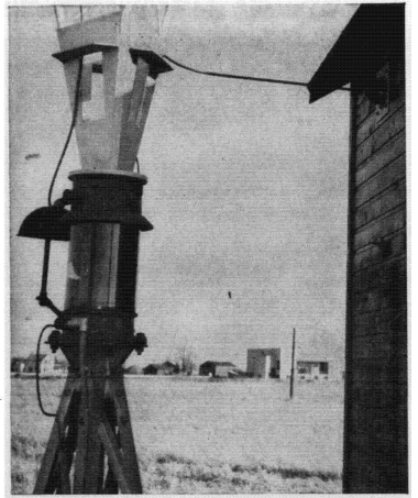
| FIG. 2.61. Base details for a 550-foot broadcast vertical radiator with tower-lighting transformer and coupling-house entrance connection. Radio Station CBK, Watrous, Saskatchewan, Canada. |
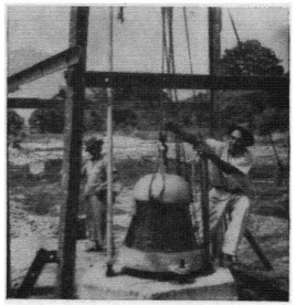 |
| FIG. 2.62. The first step in the construction of a guyed vertical radiator for broadcasting - setting the base insulator. This photograph was taken in Peru. (Photograph courtesy of R, E. Lee.) |
 |
| FIG. 2.63. A safety-core oil-filled tower-base insulator with a tower-lighting transformer and safety gap assembled. (Photograph courtesy of A. 0. Austin.) |
 |
| FIG. 2.64. Base insulator of the Austin oil-filled safety-core type with the tower-lighting transformer located inside the base insulator, at Station CKLW. (Photograph courtesy of RCA Victor Company, Ltd., Montreal.) |
 |
| FIG. 2.65. Detail of guyed tower base with radial ground screen, toroidal tower-lighting transformer, and very-high-frequency feeder isolation network (in box). This is one radiator of a six-element array at Station KTBS. (Photograph courtesy of W. M. Witty, Dallas, Texas.) |
 |
| FIG. 2.66. View of Station KTBS six-element directive array. Note pylon antenna for frequency modulation on top of third radiator from the left. (Photograph courtesy of W. M. Witty, Dallas, Texas.} |
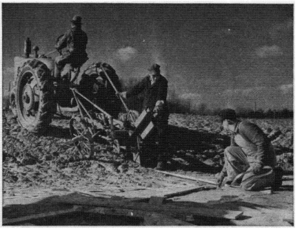 |
| FIG. 2.67. A tractor-drawn wire plow for burying ground wires. The plow blade is of sheet steel that cuts a thin furrow. The wire is fed into the furrow as the plow advances. Horse-drawn hand plows of similar principle are often used. |
 |
| FIG. 2.68. View inside antenna coupling house, showing part of the antenna coupling-network elements, the antenna grounding switch, monitoring rectifier, plate-glass window insulator for antenna lead, and the base of the guyed vertical radiator. Radio Station WTAM, Brecksville, Ohio. (Photograph courtesy of National Broadcasting Company.} |
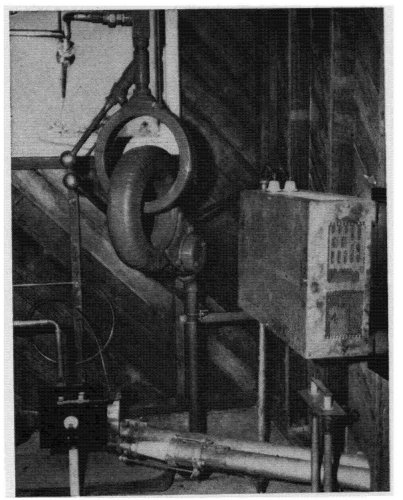 |
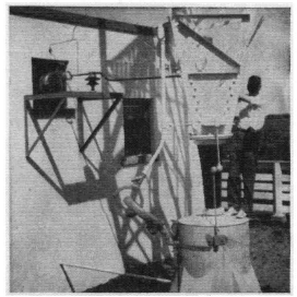
| FIG. 2.69. Antenna coupling-house interior for a broadcast station (WNBC) with a plate-glass window insulator, Austin tower-lighting transformer, a monitoring rectifier, and the end of a 3 1/2-inch concentric feeder, (Photographed during station construction. Courtesy of National Broadcasting Company.) |
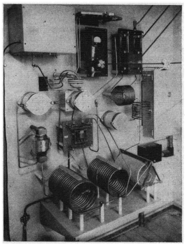 |
| FIG. 2.70. View of antenna coupling network for one element of four-element array (night pattern) and two-element array (day pattern) for Station CKLW (50 kilowatts). The coupling, phasing, and monitoring components, with switching from day to night patterns, are assembled openly and located in a cabin. (Photograph courtesy of RCA Victor Company, Ltd., Montreal.) |
|

 Medium-frequency Broadcast Antennas


