| Radio Antenna Engineering is a free introductory textbook on radio antennas and their applications. See the editorial for more information.... |

|
Home  High-frequency Antennas Horizontal Half-wave-dipole Antenna System Radiation Pattern High-frequency Antennas Horizontal Half-wave-dipole Antenna System Radiation Pattern |
||||||||


|
  |
|||||||
|
Radiation PatternAuthor: Edmund A. Laport
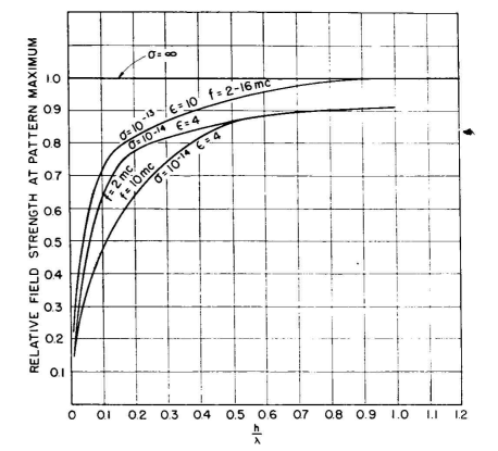
where a is the angle to the horizon and h is the height above ground in electrical degrees. The values of a at which nulls and maximums occur can be found by equating this to 0 and 1.0, respectively. For heights greater than 180 degrees there will be multiple nulls and maximums, the number increasing with the height. Vertical patterns from this equation are given in Fig. 3.15, and a chart giving the angles of nulls and maximums is given in Fig. 3.16. In most cases these patterns are used for typical imperfectly conducting grounds such as are encountered in practice. However, to compute the precise pattern that will result from the antenna over ground of the type present at a specified location, its conductivity a and inductivity e and the frequency / of operation must be determined and used in the following equation:
Here, K is the complex surface-reflection coefficient for horizontal polarization as found from the following equation:
The phase angle at reflection from the ground is always 180 degrees with a horizontal dipole. The magnitude of K varies with a for fixed ground constants. In this equation, ε is the ordinary dielectric constant of the soil, σ is the conductivity in electrostatic units, which is 9·1020 times the conductivity in the more frequently used electromagnetic units, and f is the frequency in cycles. The effect of ground loss on the maximum field strength, in comparison with perfectly conducting ground giving zero ground loss, is shown in Fig. 3.17. These data are approximate but show the importance of ground loss for small heights. This equation influences the pattern primarily with respect to the decrease in the amplitude of the maximums and the slight filling of the nulls due to incomplete cancellation of direct and reflected fields, as compared with perfectly reflecting ground. The angles of maximums and minimums are only slightly affected and for most practical uses may be considered to be the same.
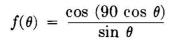
If the field about a dipole in free space were uniform (spherical pattern), the vertical pattern for the horizontal dipole above ground would be the same in all directions with respect to the antenna. But the half-wave dipole itself is directional, its pattern in free space when center-fed conforming to the equation
where θ is the angle from the antenna axis. The value of this function is 0 at 0 and 180 degrees (in the directions of the axis) and is maximum at 90 degrees (normal to the axis). Therefore, the antenna should be oriented so as to be perpendicular to the direction in which maximum radiation is desired in point-to-point applications or at the best compromise orientation in broadcasting applications. The use of simple horizontal dipole antennas for long-distance service requiring multihop ionosphere transmission has serious disadvantages because its broad vertical pattern, or in some cases a multilobe pattern, contributes to multipath interference and delays. To obtain acceptable performance in this regard, antenna arrays are necessary to obtain an optimum vertical radiation pattern for minimizing multipath phenomena.
|
||||||||
| Home High-frequency Antennas Horizontal Half-wave-dipole Antenna System Radiation Pattern |
|
|||||||

Last Update: 2011-03-19