| Radio Antenna Engineering is a free introductory textbook on radio antennas and their applications. See the editorial for more information.... |

|
Home  High-frequency Antennas Universal Antennas High-frequency Antennas Universal Antennas |
||||||


|
  |
|||||
|
Universal AntennasAuthor: Edmund A. Laport
A single antenna used for a number of frequencies also has the characteristic of widely different input impedances so that there cannot be a universal impedance match. This necessitates the switching of individual impedance-matching networks for each frequency or the readjustment of the coupling circuits for each frequency.
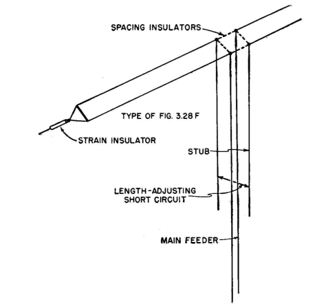
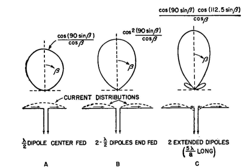
When service to a fixed point or along a fixed direction is wanted, the double dipole is useful because at least the maximum field strength is always radiated in the same direction as the frequency is changed over a range of more than 2 to 1. However, the vertical beam angle will change with frequency if the physical height remains fixed. Figure 3.31 represents a very useful form of simple antenna which can be used over a range of frequencies of 2 1/2 to 1. A different matching stub or other impedance-matching device can be used for each operating frequency within this range, if necessary. The merit of the system is that the radiation pattern maintains a constant direction normal to the antenna over the entire range, though the beamwidth of the pattern changes. Where one antenna must be used for day and night frequencies over a given fixed path, this antenna is useful. It is dimensioned to have a length each side of center of about 225 degrees at the highest desired working frequency which gives the current distribution and pattern shown in Fig. 3.31C. At a slightly lower frequency the length each side of center will be one-half wavelength, and the system, as shown in Fig. 3.31B, is two collinear cophased dipoles.
At a frequency one-half this last value, the system becomes a single center-fed half-wave dipole as shown in Fig. 3.31A. At a still lower frequency, the antenna would be electrically shorter than one-half wavelength, and its pattern would become a tangent circle. Antennas of the traveling-wave type, such as rhombicsland inverted V's, can be adjusted to have a relatively uniform input impedance over a wide range of frequencies, but the radiation pattern varies with frequency. In applying these antennas, care must be taken to determine that the variation in the pattern varies with frequency in an acceptable manner, to provide the desired service without excessive compromise and without demanding the use of excessive power.
|
||||||
| Home High-frequency Antennas Universal Antennas |
|
|||||
Last Update: 2011-03-19