| Radio Antenna Engineering is a free introductory textbook on radio antennas and their applications. See the editorial for more information.... |

|
Home  High-frequency Antennas Folded Dipoles High-frequency Antennas Folded Dipoles |
||||||||||||


|
  |
|||||||||||
|
Folded DipolesAuthor: Edmund A. Laport
The folded dipole is a radiator with a controllable resistive impedance at the feed point. It can therefore be designed to match a particular balanced feeder impedance. To control the feed-point impedance by controlling the current division in the wires of the folded dipole, the number, spacings, and radii of the conductors can be varied if necessary.
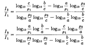
It is easily demonstrated by logarithmic-potential theory (for example, see Chap. 6) that, for a folded dipole of the type of Fig. 3.28A having two parallel conductors of radius ρ1 and ρ2 and a center-to-center spacing a (all in the same units of measurement), the ratio of the currents I1 and I2 in these two conductors is
The total antenna current is divided between the two conductors in this ratio. A three-wire folded dipole of the type of Fig. 3.28B provides an endless number of possible combinations of conductor radii and mutual spacings.
If conductors 1, 2, and 3 have radii ρ1, ρ2, and ρ3, respectively, and mutual center-to-center spacings of a between 1 and 2, b between 2 and 3, and c between 3 and 1, the current ratios between I1, I2, and I3 are given in the following equations
The total antenna current for the folded dipole comprises the sum of the component currents I1, I2, and I3. If I0 is the total antenna current and If is the relative portion of this current in the fed wire of the folded dipole, then the feed-point impedance Zf is related to the center-point impedance Za of the same dipole as a simple (nonfolded) system in the following way:
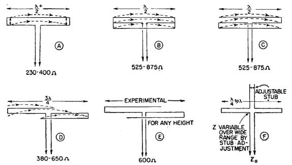
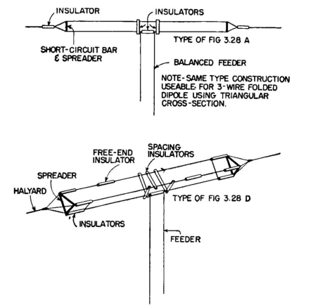
When half of a folded dipole is used as a vertical antenna operating against ground, the system is called a "folded unipole" or sometimes a "folded monopole." The same principles of current distribution among the conductors will apply as for the folded dipole. The impedances of the unipole will be exactly one-half of those of the equivalent dipole when the ground plane is perfectly conducting. A folded unipole is a form of multiple tuning, and the principle has been discussed in Chaps. 1 and 2. In high-frequency applications it is practical to use equal-radius wires for the construction of folded dipoles. The types of folded dipoles suitable for high-frequency applications include those shown in Fig. 3.28. The fact that a folded dipole has generally a larger cross section than a simple dipole gives it a greater intrinsic bandwidth; but this effect is derived wholly from its equivalence to a cage antenna. The bandwidth of a folded dipole depends upon exactly the same geometrical factors as a simple dipole. The direct match between the folded dipole and its feeder adds a further increment to the bandwidth of the system because there is then no excess energy storage to produce selectivity in the impedance-matching circuits. Figure 3.28A shows the elementary two-wire folded dipole. Experience has shown that its adjustment to match precisely a balanced feeder is facilitated by making the outside length slightly greater than one-half wavelength and then placing short circuits between the two wires a small distance in from their ends to obtain the correct center-point resistance. This adjustment should be made for the height at which the dipole will operate, because the impedance will be dependent upon height above the ground. Figure 3.28 shows five other possible versions of folded dipoles, adaptable to various feeder impedances. All of the folded dipoles shown, constructed to the indicated dimensions, have a single-lobe pattern with its maximum normal to the antenna axis. Those with lengths greater than one-half wavelength will have sharper lobes. The three-wire forms are best made in the form of a triangular cage, as shown in Fig. 3.29. A simpler construction but having unequal division of current among the three wires is to place all wires in one plane.
The form shown in Fig. 3.28F has an input resistance which is adjustable by varying the length of the stub in the second leg of the antenna by the movable short circuit (see Waidelick, D. L. Folded dipoles may be used as elements in directive arrays when greater bandwidths and great for power-handling capacities per dipole are required than are feasible with single-wire dipoles. For very high power arrays, where potential limitations become a governing design factor, folded dipole elements provide a means for using matched feeders throughout the system, thus avoiding the excessive potentials common to standing-wave feed systems.
|
||||||||||||
| Home High-frequency Antennas Folded Dipoles |
|
|||||||||||


 :
: 

Last Update: 2011-03-20