| Radio Antenna Engineering is a free introductory textbook on radio antennas and their applications. See the editorial for more information.... |

|
Home  High-frequency Antennas Horizontal Directivity of Lines of Cophased Dipoles High-frequency Antennas Horizontal Directivity of Lines of Cophased Dipoles |
||||||||||


|
  |
|||||||||
|
Horizontal Directivity of Lines of Cophased DipolesAuthor: Edmund A. Laport
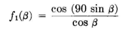
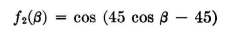
where β is measured from the normal to the dipole. A horizontal line of collinear cophased dipoles has a pattern that can be computed on the basis of isotropic radiators located at the center of each, with a magnitude proportional to the dipole current, and multiplied finally by the dipole factor f1(β). Thus, for n collinear dipoles with half-wave spacing center to center, the field-strength pattern for equal dipole currents can be computed from the following equations: For n even: For
A set of such patterns is shown in Fig. 3.41. Appendix V-B can be used in the synthesis of such patterns. The space-time reference point for these equations is the geometrical center of the system. Another form in which these patterns can be expressed is
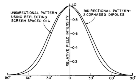
These collinear half-wave dipole patterns are for free-space conditions. When they lie parallel to ground, the pattern becomes what is commonly called the horizontal pattern, though actually it is a horizontal plan view of the pattern. When an identical line of radiators is located at the same height above ground, spaced one-quarter wavelength from it, and the system excited so that their currents are equal but differ in phase by 90 degrees, the horizontal pattern is the free-space pattern for one line of radiators multiplied by the couplet factor
Patterns of this type are shown in Fig. 3.42. When the system of collinear half-wave dipoles is parallel to a perfectly reflecting plane, the pattern f0(β) in the plane through the radiators and their images will be the same as for the original line of dipoles, multiplied by the reflector factor f3(β) = sin (d cosβ). Then
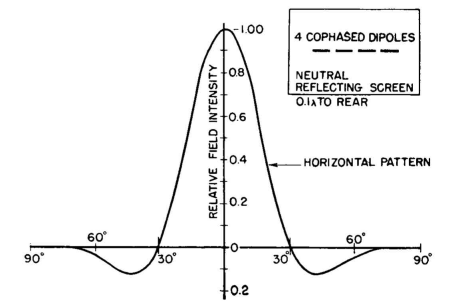
When the electrical distance d from the reflector is less than 30 or 40 degrees, f3(0) = cos β very nearly. Of course β must lie in the plane through the dipoles and their images. Figures 3.43, 3.44, and 3.45 show the patterns for two, four, and six collinear half-wave dipoles with equal currents when placed in front of a perfectly reflecting surface.
Arrays of parallel vertical half-wave dipoles spaced one-half wave-length have patterns in the horizontal plane specified by
Patterns for straight rows of vertical dipoles each having unit current, cophased, are shown in Fig. 3.46.
|
||||||||||
| Home High-frequency Antennas Horizontal Directivity of Lines of Cophased Dipoles |
|
|||||||||


Last Update: 2011-03-19