| Radio Antenna Engineering is a free introductory textbook on radio antennas and their applications. See the editorial for more information.... |

|
Home  High-frequency Antennas Vertical Directivity of Stacked Horizontal Dipoles High-frequency Antennas Vertical Directivity of Stacked Horizontal Dipoles |
||||||||||


|
  |
|||||||||
|
Vertical Directivity of Stacked Horizontal DipolesAuthor: Edmund A. Laport
This process can lead to very high and expensive structures. Yet such is the problem of obtaining a high concentration of energy at very low angles. In the following equation, h is the electrical height of the lowest dipole above perfect ground. The other dipoles are assumed to be spaced at half-wavelength intervals with equal currents. The principal vertical pattern, using the method of adding the patterns for individual pairs formed by each dipole and its image (see Appendix V-A), using the geometry of Fig. 3.37, is
where N is a normalizing factor and n the total number of dipoles in the stack. Each dipole in the stack introduces a term in this equation. When h is a multiple of 180 degrees, quick computation can be made with the aid of Appendix V-A. The principal vertical pattern can also be written in another form when the number of dipoles is an integral power of 2.
The first cosine factor is the pattern for the uppermost pair of dipoles. The second factor is the free-space pattern for two cophased pairs of dipoles. The third factor is the effect of the height of the array above perfectly conducting ground to the middle of the dipole system (not to the lowest dipole as in the preceding example).
The fourth factor is the dipole orientation factor, which is unity when the dipole is horizontal and when it is vertical is the familiar dipole-pattern factor
In a two-stack array, advantage can be taken of the additional gain that results from a spacing of 0.625 wavelength, the optimum spacing from a gain standpoint. This requires a symmetrical feed arrangement similar to that shown in Fig. 3.38. For an array of this type, the vertical pattern through the main beam, assuming perfectly conducting ground, is
Vertical stacks of dipoles are most conveniently fed in cascade from the bottom upward. It is preferable to use half-wave spacing between dipoles so that the dipoles can be equally excited by the standing waves on the vertical feeder. It must be remembered that ordinary cascade feeding includes the attenuation that occurs from bottom to top, which means that there is a consequent tapering of the dipole currents upward along the stack. Mutual impedances tend to equalize this somewhat. The reduction of current in successive dipoles causes the pattern to be tilted upward more than that for equal currents. This effect increases with an increase in the number of stacks. This upward tilting of the pattern can be corrected by feeding the stack from its center and propagating the currents equally upward and downward from the feed point. Since the expense of high structures is incurred to obtain low angles of radiation, attention to this effect is important in obtaining maximum effectiveness from this height. A curtain of parasitic (or energized) reflectors or a passive screen reflector of untuned wires influences the vertical pattern because of the additional interference of the fields due to the depth of the array. This effect is used to obtain further suppression of high-angle lobes as well as to suppress backward radiation. A passive reflector of adequate area is a very effective device for suppressing backward radiation. When the reflector wires, parallel to the active radiators, are spaced one-tenth wavelength or less, very little energy is radiated backward and most of what does leak backward is due to diffraction around its edges. The backward-diffraction field is reduced as the directivity of the active curtain is increased. With a highly directive active curtain, the area of the passive reflector can be made equal to the area of the active curtain with relatively small diffraction leakage. When a stack of four horizontal dipoles spaced 180 degrees is placed in front of a passive reflector, the vertical pattern in the principal vertical plane normal to the forward curtain becomes, assuming perfect earth and perfect infinite reflector,
The first two factors account for the active curtain, the third for the height of the middle of the curtain, and the last the passive reflector spaced d degrees from the curtain. The application of this equation to a system of two lines of horizontal dipoles spaced 180 degrees with a mid-height of 450 degrees and spaced 36 degrees from a passive reflector, with equal cophased currents in the active dipoles, is shown in Fig. 3.39, step by step. The curtain factor, the height factor, and the reflector factor are all shown, as well as their evolution to the final pattern, shown shaded. When an identical curtain of parasitically excited dipoles is used for the reflector, the pattern is indeterminate because of complicated mutual effects similar to those shown in Fig. 3.35. The maximum forward field strength is not coincident with minimum backward field. The system is quantitatively so complex that any analysis must be regarded as empirical, although most large dipole arrays used to date have been of this type. It is therefore useless to formulate the pattern shape in the backward direction, but in the first quadrant of the forward direction one may use the approximate relation, for four stacked cophased dipoles,
In this equation the commonly used spacing of one-quarter wavelength between radiator curtain and reflector curtain was assumed in the values used in the last factor. A simple form of cubical array can be illustrated by the following case: It is desired to obtain a radiation pattern, substantially unidirectional, giving a moderately low angle of radiation in the forward direction in the vertical plane and maximum suppression of other radiation lobes in forward and backward directions consistent with a minimum number of radiators and economical design. Such a need often arises in directive broadcasting on the tropical broadcast frequencies where arrays of large electrical size are uneconomical or impractical.
If we examine the chart of pair patterns, we shall find that a pair with 225 degrees spacing and a phase difference of 45 degrees has a pattern with a submaximum along the line of the radiators in one direction and zero in the other. Two other large lobes occur almost normal to the array axis. This pair has the pattern
which has zeros at 37 and 180 degrees. If now we place the axis of this pair parallel to ground at a height of one-half wavelength, the height factor will have the equation
which has nulls at 0, 90, and 180 degrees. The zero at 90 degrees will split the major lobe from the radiator pair. What remains is still very large at about 120 degrees (60 degrees above the horizon in the backward direction), and further suppression is desired. The pattern chart is examined again, and it is noted that a cophased pair spaced 0.75 wavelength has a zero at 42 degrees each side of the line normal to the pair.
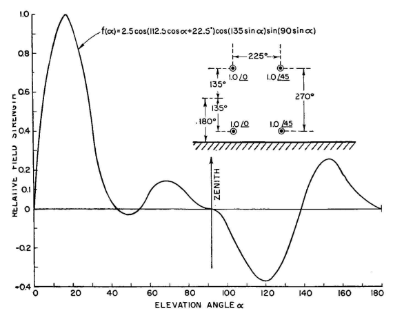
This suggests that each of the original radiators may be replaced by such a cophased pair of radiators centered on the location of the original dipoles, with their axes vertical. Thus the array as seen from the side consists of four dipoles at the corners of a rectangle, with a height of 0.75 wavelength (270 degrees) and a width of 0.625 wavelength (225 degrees) and with an average height of 0.5 wavelength from ground (180 degrees). This brings the two lower radiators 45 degrees above ground, the upper ones 315 degrees. In the vertical plane, with this configuration, the last pair has the pattern
In the vertical plane this entire array of four dipoles will have the pattern
When this is computed and plotted we obtain Fig. 3.40. In this figure, the pattern has been "normalized" to restore its maximum value to unity. There are now zeros at 0, 42, 54, 90, 138, and 180 degrees. The maximum field strength occurs at 16 degrees, at which angle the unnor-malized maximum value of the above equation is about 0.4. To bring this to 1.0, a normalizing factor of N = 2.5 is applied to the equation, which merely enlarges the pattern. A normalizing factor larger than 1.0 means that the radiation resistance of the system has been reduced below normal value, and to obtain normal fields, relatively large currents will be necessary in the radiators. Large currents will result in high system potentials. Both these facts caution the engineer to be considerate of system losses, or low radiation efficiency may result. This condition is characteristic of all radiating systems that give theoretically large gains in relatively small space. This will be confirmed if one makes the computations for the radiator impedances, taking into account all the mutual impedances between radiators and images. A normalizing factor of 2.5 is not excessively large, indicating that with provisions for minimizing conductor and insulation losses, and also ground losses, good working efficiency may be realized. The proximity of the lower radiators to ground suggests the need for improving the effective conductivity of the ground, which can be done by using a surface ground screen of wires spaced 0.05 or 0.1 wavelength and parallel to the dipoles. If the radiators of this array consist only of single horizontal half-wave dipoles, the horizontal pattern will have the formula
If additional horizontal directivity is wanted, each radiator may consist of two or more collinear half-wave dipoles.
|
||||||||||
| Home High-frequency Antennas Vertical Directivity of Stacked Horizontal Dipoles |
|
|||||||||


Last Update: 2011-03-19