| Radio Antenna Engineering is a free introductory textbook on radio antennas and their applications. See the editorial for more information.... |

|
Home  High-frequency Antennas Radiation Patterns for Dipole Arrays High-frequency Antennas Radiation Patterns for Dipole Arrays |
||||||


|
  |
|||||
|
Radiation Patterns for Dipole ArraysAuthor: Edmund A. Laport
The pattern for a dipole array in the main vertical and horizontal directions of interest can be computed separately by the methods outlined in the preceding pages. These patterns are all in terms of relative field strength. If it is desired to compute the radiation patterns in terms of relative power, the field-strength values are to be squared everywhere.
Directivity is desired in two major planes, called generally the "horizontal" (plan view) and the "vertical" (side view). At times the patterns at other angles may be necessary. Any desired directivity is obtained by separately utilizing the interference obtained by ground and from reflector-image radiations for the vertical patterns and the interference between the linear current distributions together with any reflector action for the horizontal pattern. The independent control of the pattern in the two major planes is a valuable property of dipole arrays and often dictates their adoption for certain applications. Such antennas are classed generally as broadside antennas, since the main beam is virtually normal to the plane of the dipole curtain,
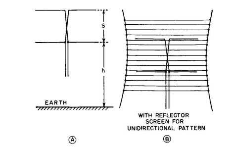
One of the simplest arrays with radiation control in the two major planes is the Lazy H, shown in Fig. 3.48A. In Fig. 3.48B it is shown with a passive reflector of wires for a unidirectional pattern. It consists of four horizontal half-wave dipoles, 2 by 2, voltage-fed from a central feeder. Using larger numbers of elements, the size of a dipole array can become very large, especially when very low angle radiation and a very sharp beam in the horizontal plane are required. Figure 3.49A shows the dipole arrangement for a 4 by 4 curtain with separate feed for each half and provisions for slewing the horizontal beam by changing the relative phases in the two halves. Figure 3.49B shows a 6 by 4 curtain with center feed. The patterns for all extensive dipole arrays using equal currents in the individual dipoles are characterized by secondary lobes of moderate size. This is illustrated in Figs. 3.50, 3.51, and 3.52, except that in these figures the complete pattern for the forward half is displayed in terms of relative power distribution, instead of the usual field-strength distribution.
|
||||||
| Home High-frequency Antennas Radiation Patterns for Dipole Arrays |
|
|||||

Last Update: 2011-03-19