| Radio Antenna Engineering is a free introductory textbook on radio antennas and their applications. See the editorial for more information.... |

|
Home  High-frequency Antennas Secondary Lobes Suppressing Secondary Lobes High-frequency Antennas Secondary Lobes Suppressing Secondary Lobes |
||||||||||||


|
  |
|||||||||||
|
Suppressing Secondary LobesAuthor: Edmund A. Laport
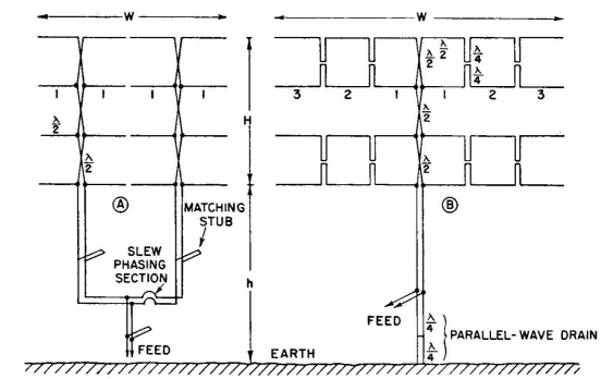
In the formulas for radiation patterns use can be made of the fact that a null in any one factor of the equation produces a null in the final pattern at the same angle. By placing the nulls in one factor at the angles of secondary lobes in the other factors, these secondary lobes can be split and reduced in amplitude almost as desired. This principle was used in Chap.2 and will be illustrated here by an example.
A single horizontal dipole and its image form an antiphased pair whose pattern has nulls located as shown in Fig. 3.16. For the maximum to be between 6 and 8 degrees the first null must be at about 15 degrees. From Fig. 3.16 we find that the height of the dipole must be 1.94 wavelengths above ground (700 degrees). In addition to the null at 15 degrees there will be other nulls at 31 and 50 degrees. A cophased pair of dipoles, centered at 700 degrees, can now be substituted for the single dipole. For this pair the spacing can be made such as to bring another null midway between 15 and 31 degrees, where a large secondary lobe should exist. A cophased pair with a null at, say, 22.5 degrees has to have a spacing of 480 degrees. The pair pattern with this spacing has only this one null. So far it is known that the combination pattern has nulls at 15, 22 1/2, 31, and 50 degrees.
Hayes and McLarty.) It is now noted that there is a large angle between 31 and 50 degrees in which a large lobe can exist. The next step is to substitute for each of the former two dipoles a pair of cophased dipoles centered at 700 degrees plus and minus 240 degrees. The patterns for these two pairs are identical, and a spacing is chosen that will bring a null at about 40 degrees. The null-angle chart shows that this would result from a pair spacing of 280 degrees. ´
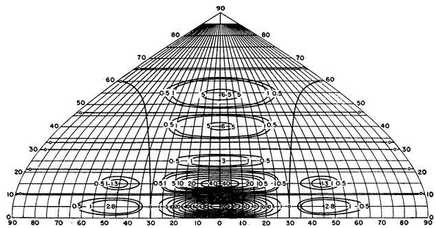
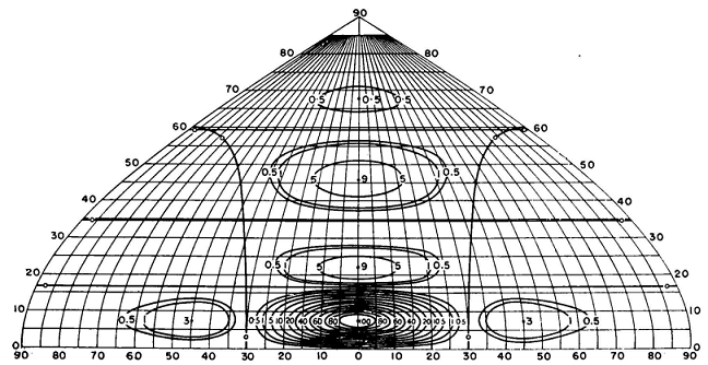
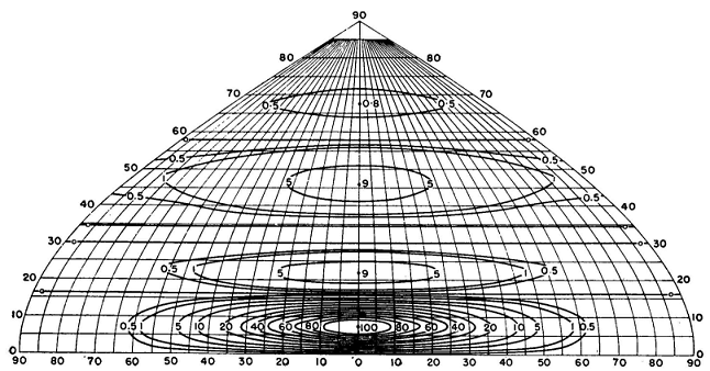
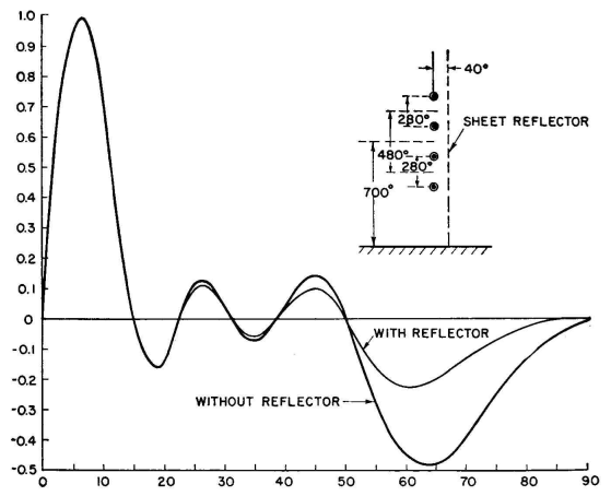
The array now consists of four dipoles, with equal cophased currents, arranged vertically at heights of 320, 600, 800, and 1,080 degrees. The vertical pattern for this array has nulls at 15, 22 1/2, 31, 40, and 50 degrees. The geometry now permits a computation of the full pattern for examination. The result is shown in Fig. 3.53, with and without a screen reflector. As a first approximation the secondary lobes are suppressed 16 decibels or more at all angles that would cause multipath delays. If the suppression of the uppermost lobe had to be increased, a further extension of the method to put a null at about 60 degrees would provide a possible solution. Obviously, this characteristic of the pattern equations in factor form adapts itself more readily to the solutions of problems of this kind than would the form having a series of terms added together. The latter form, however, lends itself more conveniently to binomial, Fourier, and Tchebysheff polynomial distributions, where the current amplitudes across the curtain are graded in some systematic manner to produce a prescribed pattern shape.
|
||||||||||||
| Home High-frequency Antennas Secondary Lobes Suppressing Secondary Lobes |
|
|||||||||||
Last Update: 2011-03-19