| Radio Antenna Engineering is a free introductory textbook on radio antennas and their applications. See the editorial for more information.... |

|
Home  High-frequency Antennas Horizontal Rhombic Antenna Introduction High-frequency Antennas Horizontal Rhombic Antenna Introduction |
||||||||||
| See also: Radiation Characteristics, V Antennas | ||||||||||


|
  |
|||||||||
|
Horizontal Rhombic AntennaAuthor: Edmund A. Laport
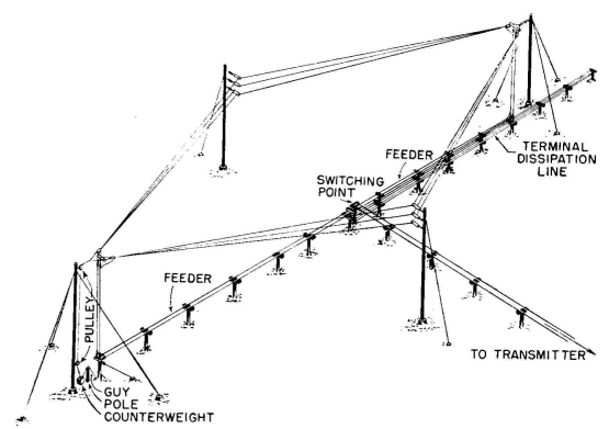
The commonest practical form of high-frequency antenna using the traveling-wave principle is the horizontal rhombic antenna, constructed as shown in Fig. 3.77. It is widely used in high-frequency applications for both transmitting and receiving. It has some marked advantages and disadvantages.
The disadvantages include large amount of land required; loss of power in the terminating load; a multiplicity of lobes of radiation in almost all directions, in addition to some rather large secondary lobes under the best conditions of design; compromises necessary from a propagation standpoint as the radiation pattern changes with frequency; limitation of gain and signal-to-noise ratio due to the multiplicity of radiation lobes; difficulty of predetermining its complete performance due to the complications of computation and to the effects of attenuation and partial standing waves always present in practice; and inability to control the horizontal and vertical patterns separately. For optimum performance, a rhombic antenna should be designed for use at one frequency or a very small band of frequencies, the pattern for which is best suited to the propagation conditions of the space circuit.
Usually about all that a designer attempts to compute about this system is the characteristic of the main lobe. The enormous labor of computation has obscured its complete radiation characteristics. There has been widespread confusion between the radiation performance of the horizontal rhombic and its circuitry. The input impedance may be uniform over a frequency range of 8 to 1 but its radiation characteristics are seldom satisfactory over more than 2 to 1 range.
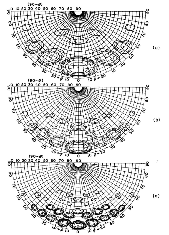
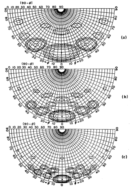
The patterns shown in Figs. 3.78 and 3.79
The outer periphery of each chart is the horizon of a flat earth, and the center is the zenith. The contours are in 3-decibel steps, the smallest shown being only 18 decibels below the amplitude of the main beam. There are many others below this value in the forward half of the hemisphere and also in the rear half, which is not shown. Imperfect construction undoubtedly accentuates these spurious lobes beyond the relatively ideal theoretical conditions represented in these figures. Christiansen has described methods by which these patterns can be improved, using tiered, broadsided and overlaid rhombic elements.
|
||||||||||
| Home High-frequency Antennas Horizontal Rhombic Antenna Introduction |
|
|||||||||


Last Update: 2011-03-19