| Radio Antenna Engineering is a free introductory textbook on radio antennas and their applications. See the editorial for more information.... |

|
Home  High-frequency Antennas V Antennas High-frequency Antennas V Antennas |
||||||||||||
| See also: Horizontal Rhombic Antenna | ||||||||||||


|
  |
|||||||||||
|
V AntennasAuthor: Edmund A. Laport
The V antenna uses two long wires in a balanced arrangement parallel to ground, with a mutual orientation which causes the main lobe from the two sides to add along the axis of the V at some desired elevation angle. The tilt of the horizontally polarized beam depends upon the length of a side, the angle formed by the sides, and also upon the height above ground.
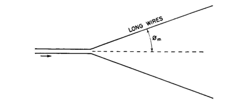
1. The structural design is simple and economical. 2. The electrical circuitry is simple, when they are fed from the apex. 3. High gain is secured at relatively low cost. 4. They use low supporting structures but require large areas. 5. The horizontal beam width and the elevation of the point of the main beam are not separately controllable but are mutually dependent on the geometry of the array. Figure 3.73 shows a plan view of the electrical parts of a simple horizontal V made up of two wires, end-fed from a balanced feeder.
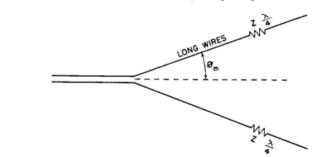
In this form, there would be standing-wave excitation due to reflections from the open outer ends of the radiating wires. This system would therefore be bidirectional. The apex angle has a value somewhat less than twice the angle between the wire and the maximum of the first cone of radiation (θm) for the electrical length of the wire, as determined from Fig. 3.67. To obtain a unidirectional V antenna, the principle shown in Fig. 3.71
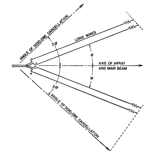
can be applied to each side, as shown in Fig. 3.74, so that traveling waves result. It must be recognized that the geometry of long wires that causes the first radiation cones to add along the axis of the V is not that which fully cancels these same cones on the outer sides of the wires. There is characteristically a residual outer lobe of considerable amplitude at an angle of 2θm each side of the axis. It is possible to reduce these unwanted lobes by employing the principle indicated in Fig. 3.72, where a second parallel wire placed on each side, properly spaced, staggered, and excited, will do the necessary canceling at the angle 2θm from the axis. For a traveling-wave system, this resulting configuration is shown in Fig. 3.75. Traveling waves can be obtained by other methods of terminating the wires so that the excess energy arriving at the ends is dissipated.
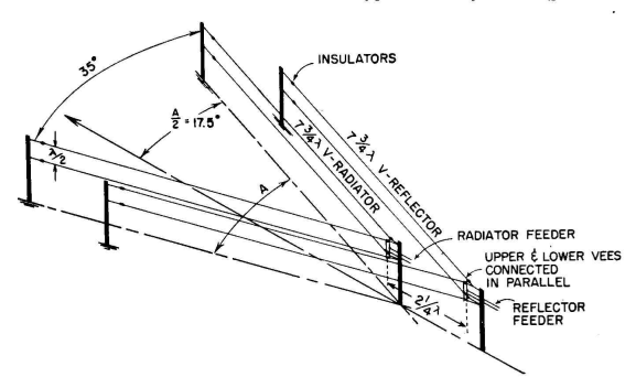
One such method is to continue each wire outward for a considerable distance very near to ground, after tilting them downward toward the ground from the antenna proper. This is a compromise measure, so devised as to permit very little radiation from the extension wire and at the same time to increase its attenuation rapidly by proximity to ground. The extension wires may be several wavelengths long but are necessarily of such a length that there is some 20 decibels of attenuation. The outer ends may be grounded (providing static drain) or left open-circuited. The extension wires may also be of iron to increase attenuation. In some past applications, the entire antenna has been tilted, using one high support at the apex of the V and sloping both sides toward ground to the point where the extension wires can continue onward just above the ground. The simplicity of such a structure is very attractive from a cost standpoint, but its use must depend upon the radiation pattern in relation to propagation requirements. Figure 3.76A is an isometric sketch of the arrangement of the RCA Model D antenna of the unidirectional V type excited by standing waves.
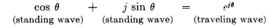
One V acts as the reflector for the other to obtain unidirectivity horizontally polarized along the axis in the direction of the open end of the V. In this design, two wires are employed in each side of each V one above the other, cophased and spaced one-half wavelength. The length of each wire is an odd number of quarter wavelengths, which provides appreciable reduction of the amplitudes of some of the minor lobes, as shown in Fig. 3.66. The reflector is excited in quadrature-phase relation with respect to the inner V. A unidirectional V antenna can be made by combining the fields from two standing-wave systems in close proximity, one obtained from a cosine distribution and the other from a sine distribution in quarter-phase relationship. This is an embodiment of the familiar Argand principle expressed by
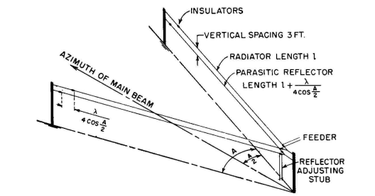
The geometrical parameters are shown in Fig. 3.76B, together with the elementary circuitry. The lower V, consisting of two wires longer than the driven V and using an adjustable stub section at its apex, is parasit-ically excited by the field of the driven V. The correct phasing to achieve the quadrature relation between the driven V and the parasitic
V is obtained by adjusting the stub section at the apex. This system is known as the RCA Model G antenna.
|
||||||||||||
| Home High-frequency Antennas V Antennas |
|
|||||||||||
Last Update: 2011-03-19