| Radio Antenna Engineering is a free introductory textbook on radio antennas and their applications. See the editorial for more information.... |

|
Home  Radio-frequency Transmission Lines Useful Transmission-line Configurations Two Wire Two-wire Balanced Feeder Radio-frequency Transmission Lines Useful Transmission-line Configurations Two Wire Two-wire Balanced Feeder |
||||||||


|
  |
|||||||
|
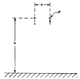
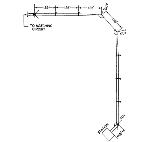
Two-wire Balanced FeederAuthor: Edmund A. Laport This is the commonest type of feeder (Fig. 4.20) for balanced operation and is used for a great variety of applications for high and very high frequencies where open-wire lines are desired. It is simple to construct and is relatively inexpensive. When used for high-power transmission, certain precautions are necessary with regard to potential gradients and details of construction. The conductor size can be increased as much as desired to increase the power-handling capacity, but beyond a point it is more economical to obtain the same effect with two or more conductors in parallel on each side of the circuit, as shown in some succeeding cases.
In all balanced feeder systems, great care must be taken to ensure that the total length of wire is exactly the same for both sides of the circuit
between transmitter and load. When passing through switching devices, transpositions, or bends or turns in the line and entering or leaving the equipment and buildings, the conductor arrangement must always be such as to provide for this essential requirement.
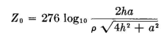
but when h ^ a,
A range of values of characteristic impedance as a function of the ratio of wire spacing to wire radius is shown in Fig. 4.23, which includes the case of small spacings where the proximity effect and the nonuniform peripheral charge distribution on the conductors come into play. In this figure, the spacing is that between the centers of the conductors. When correctly balanced to ground, the radiation from a feeder of this type with 12-inch spacing is virtually negligible up to 25 megacycles. Frequently it is necessary to route several such feeders in parallel, as is done with telephone lines. The amount of cross talk that will occur depends upon the spacing between circuits and upon the cross section of any one circuit, the length of the run in parallel, and the selectivity of the load circuit. For a given amount of cross talk between feeders, the circuits can be placed nearer each other if they are arranged to have a common neutral plane (that is, arranged with one circuit above the other) rather than with all the lines in the same plane. The latter, however, is often more convenient, even though it is necessary to use greater spacing between circuits.
To minimize cross talk, various transposition techniques may be applied as in ordinary telephony. It is difficult to place any specific limitations on tolerable cross coupling between circuits. One might believe that two parallel feeders en route to two different antennas are quite isolated if the power induced into the adjacent circuit is 40 decibels below that in the main circuit.
Yet if the antenna to which this cross talk is delivered has no selectivity to discriminate against this signal and radiates it with full antenna gain in some undesired direction, its effect can be undesirable and cause interference out of proportion to the actual power level. This sort of cross talk has not been studied much in the past, but if the most effective use of a crowded frequency spectrum is to be achieved in the future, far greater care will be needed to reduce cross talk between feeder and radiating systems. For the same reasons, directive antennas will require far greater suppression of radiations in undesired directions. Undoubtedly many existing feeder arrangements, if critically studied, would be found to have intolerable cross-talk ratios because of close proximity.
|
||||||||
| Home Radio-frequency Transmission Lines Useful Transmission-line Configurations Two Wire Two-wire Balanced Feeder |
|
|||||||

Last Update: 2011-03-19