| Radio Antenna Engineering is a free introductory textbook on radio antennas and their applications. See the editorial for more information.... |

|
Home  Radio-frequency Transmission Lines Useful Transmission-line Configurations Three Wire Three-wire Unbalanced Feeder Radio-frequency Transmission Lines Useful Transmission-line Configurations Three Wire Three-wire Unbalanced Feeder |
||||||||||||||||||||||||||


|
  |
|||||||||||||||||||||||||
|
Three-wire Unbalanced FeederAuthor: Edmund A. Laport
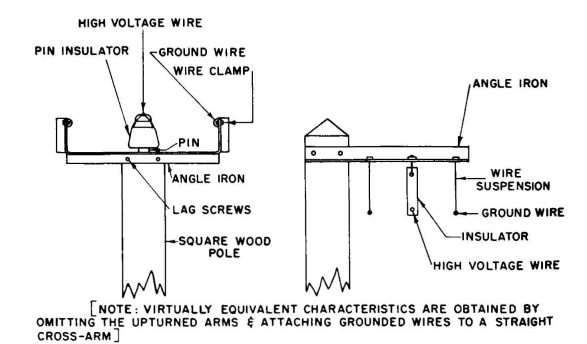
This is a one-insulator type, where the insulator supports the high-potential wire. No insulators are needed for the grounded wires in low-power applications, but in high-power applications the convergence of the electric-flux lines at the grounded wires can produce large gradients near them, causing dielectric loss in any poor insulating material near the grounded wires. The grounded wires should then be insulated.
Possible constructions for this type of line are shown in Fig. 4.6. Only a very small difference results from having the ground wires slightly below the level of the central wire. When h » a,
When ρ1 = ρ2
Some typical electrical values are:
|
||||||||||||||||||||||||||
| Home Radio-frequency Transmission Lines Useful Transmission-line Configurations Three Wire Three-wire Unbalanced Feeder |
|
|||||||||||||||||||||||||


Last Update: 2011-03-19