| Radio Antenna Engineering is a free introductory textbook on radio antennas and their applications. See the editorial for more information.... |

|
Home  Radio-frequency Transmission Lines Impedance-matching Techniques Impedance-matching Series Line Sections Radio-frequency Transmission Lines Impedance-matching Techniques Impedance-matching Series Line Sections |
||||||||||||||||||||||||||||||||||||||||||||||||||||


|
  |
|||||||||||||||||||||||||||||||||||||||||||||||||||
|
Impedance-matching Series Line SectionsAuthor: Edmund A. Laport In high-frequency practice, conditions are often favorable for the insertion of a short length of line in series with a main feeder as an impedance-matching device. When this line section has the correct characteristic impedance and length and is located at the correct position in a mismatched feeder, the standing waves can be suppressed for one frequency or a small band of frequencies.
In a two-wire balanced feeder, a reduction in Z0 can be effected by closer spacing, larger conductors, or both. Whereas an increase in Z0 is effected in the opposite manner, a large increase in Z0 may not be physically realizable.
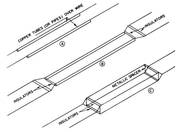
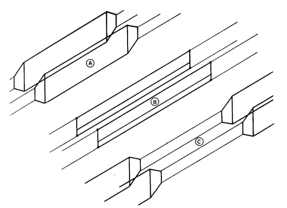
For this reason, the quarter-wave impedance-matching section will usually start at a current maximum so that it can use a characteristic impedance less than that of the main feeder. The matching section may be made with reduced characteristic impedance by using a four-wire cross section, with two spaced wires in parallel on each side, or by using much larger conductors, or by reducing the spacing between wires. For illustrations of these possibilities see Figs. 4.34 and 4.35. With a four-wire balanced line of type XVI, where there are two wires in parallel on each side of the feeder, the characteristic impedance of a quarter-wave matching section may be made lower or higher than that of the main feeder by contracting or expanding the spacings of the sides or between the sides, or by changing conductor sizes, or by increasing the number of wires in parallel, or combinations of all these. In such a feeder, this series-section method of impedance matching is convenient and practical.31,32 Figure 4.35 shows various possibilities. In this figure A and B are sections of reduced characteristic impedance, and C is a section with increased value. Figure 4.89 shows this method in use. The matching of impedances by this method is not restricted to the use of quarter-wave matching sections. In the generalized case the computations are more involved.
For this purpose the circle diagram of a transmission line is useful. Such a diagram is shown in Figure 4.58-These curves are read as follows: The abscissa of a rectangular system of coordinates is taken as the scale of resistances, and the ordinates, positive and negative, are taken as the scales for positive and negative reactances, using the same scale as for resistance. In order to make the chart as general as possible, a characteristic impedance of 1.0 is used for all computations. This makes all resistances and reactances read directly in proportional parts of the characteristic impedance of any transmission line. The focal point is 1.0 ± j0. This is the input impedance of a perfect line with Z0 = 1.0 and terminated in a resistance Rt = Z0, whatever the distance from the termination. When the line is terminated in a resistance Rt > Z0, the input impedance Zin, as a function of distance from the termination, will describe a circle enclosing Z0. This circle will be centered on the resistance axis but will be eccentric with respect to the Z0 focal point. The distances from the terminal end fall on semicircles centered on the reactance axis where Rin = 0. The direction of change of Zin with βl in degrees from the termination is clockwise from the resistance axis, starting at the right of Z0 when Rt > Z0, and sweeps a semicircle in the first 90 degrees and a full circle back to the starting point on the resistance axis in 180 degrees (one-half wavelength from the termination). To test this method with figures, read from the chart (Fig. 4.58) Rt, βl, Rin and Xin:
When Rt < Z0, the starting point is on the resistance axis to the left of the focal point and electrical length is read clockwise, starting from this axis as zero and continuing around the complete circle at 180 degrees. The chart is not marked this way, to avoid confusion, but in use one subtracts 90 degrees from the electrical lengths marked on the radial lines in the upper half of the chart and adds 90 degrees in the lower half of the chart. For example, test the following points on Fig. 4.58:
These relative values of impedance are from the resistive termination or from the current maximum or current minimum nearest to the termination when Zt is complex, or when Zt <> Z0. The ratio Rt/Z0-Q is the standing-wave ratio, marked on the confocal circles. By means of this circle diagram the impedance at any point on a mismatched feeder can be determined if the standing-wave ratio can be measured and the point of minimum or maximum current located. From the knowledge of the impedance Z/θ at any chosen point on a mismatched line, one can proceed to determine the electrical length βl00 and characteristic impedance Z00 of a matching line to terminate the main feeder in its characteristic impedance Z0.
|
||||||||||||||||||||||||||||||||||||||||||||||||||||
| Home Radio-frequency Transmission Lines Impedance-matching Techniques Impedance-matching Series Line Sections |
|
|||||||||||||||||||||||||||||||||||||||||||||||||||

Last Update: 2011-03-19