|
Vibrational Stress of Wires
Author: Edmund A. Laport
In wire systems that are tightly strung there should be a liberal allowance for the additional stress imposed by high-frequency vibration of the wires, over and above the relatively static stresses due to wind and ice loadings. The effect of transverse vibration, regardless of mode, is to increase the lateral displacement and
stretch the wire. The sum of all vibrational and static stresses should, of course, never equal the ultimate tensile strength of the wire, even after allowing for some degree of weakening with time due to fatigue of the
metal.
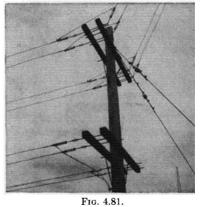 |
| FIG. 4.81. Details for several two-wire balanced lines for medium-power transmission. |
 |
| FIG. 4.82. Details showing the use of strain insulators and the use of copper splicing sleeves for terminating wires at the insulators. |
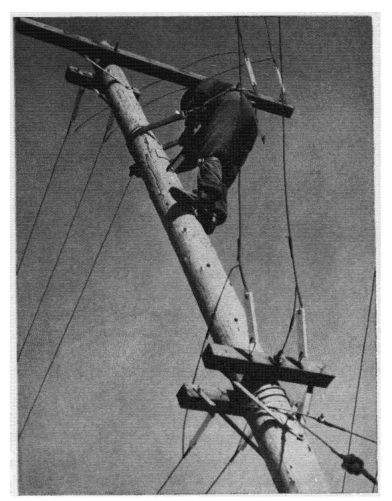 |
| FIG. 4.83. Rigger working on a pole carrying balanced two-wire feeders for high-frequency broadcasting. This typifies many applications of this style of construction and hardware for broadcasting and communication use. This photograph was taken during construction, and the lines are not in final condition. Note the use of copper splicing sleeves at insulators, the attachment of guy wires, and crossarm hardware details. (Photograph courtesy of National Broadcasting Company.)
|
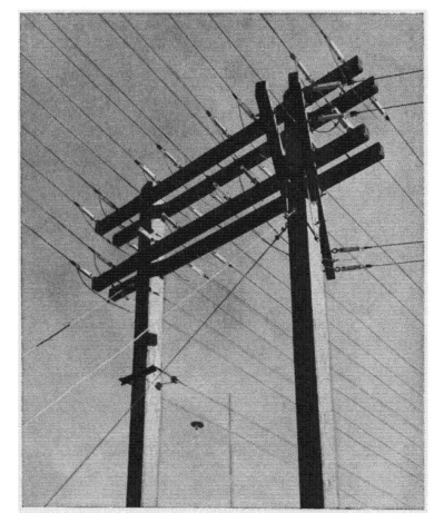 |
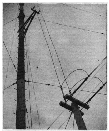
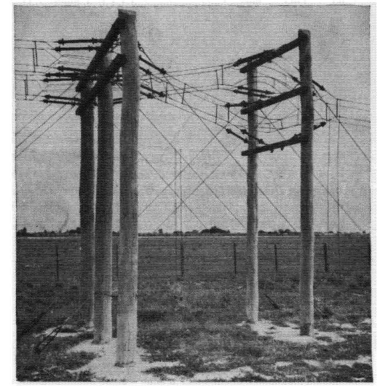
| FIG. 4.84. Strain-pole assembly for eight balanced two-wire feeders, with two feeders routed from this support to antennas to the right. These feeders are used to feed any one of eight antennas from a 50-kilowatt high-frequency broadcast transmitter. Steatite block insulators are attached to eyebolts on the crossarms by clevises. The feeder wires are formed in eyes to attach to the insulators and are closed with pressed-metal retainers. (Photograph courtesy of Radio National, Rio de Janeiro and RCA International Division.) |
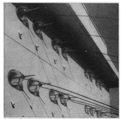 |
| FIG. 4.85. Entrance details for eight balanced two-wire feeders as used by a 50-kilo-watt high-frequency broadcast station in Rio de Janeiro. Pyrex bowl insulators (in pairs) serve as entrance insulators. Note the porcelain tubes used as ventilators to remove condensed moisture from the space in the wall between the bowl insulators. (Photograph courtesy of Radio Nacional, Rio de Janeiro and RCA International Division.) |
 |
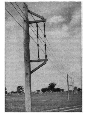
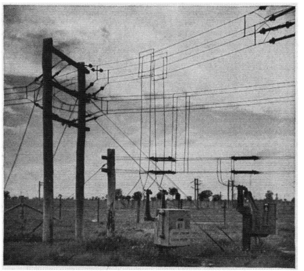
| FIG. 4.86. Details showing a terminal pole for two balanced two-wire feeders and the manner of maintaining constant tension on the vertical feeders for a beam antenna. These methods were used for transmitting 50 kilowatts for high-frequency broadcast service. The station building can be seen in left background. (Photograph courtesy of Radio National, Rio de Janeiro and RCA International Division.)
|
 |
| FIG. 4.87. Details showing the method used at the Bolinas, California, high-frequency communication station for distributing balanced two-wire feeders to several 20- to 40-kilowatt radiotelegraph transmitters. (Photograph courtesy of RCA Communications, Inc.) |
 |
| FIG. 4.88. Details showing the guying of a very high wood pole, a strain pole for a four-wire side-connected balanced feeder and the rigging details, a vertical corner, and the use of post insulators on the vertical section of the feeder. This is part of a beam system for 200-kilowatt high-frequency broadcasting at Dixon, California.(Photograph courtesy of National Broadcasting Company.)
|
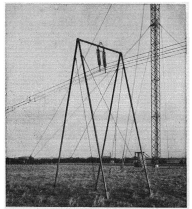 |
| FIG. 4.89. This photograph shows several interesting features. A guyed pipe framework is used instead of a pole to support a four-wire balanced side-connected feeder for high-power short-wave broadcasting in England. Two forms of impedance matching are shown: the pinched section of higher characteristic impedance at the left, and inductors in series (with center grounded to support frame) and surrounding the line insulators as a substitute for an inductive parallel stub line. A guyed steel mast for supporting high-frequency dipole arrays is seen in the background. (A British Broadcasting Corporation photograph, included here with the permission of the Institution of Electrical Engineers.) |
 |
| FIG. 4.90. A method of construction for the four-wire side-connected balanced feeder. (Photograph courtesy of Australian Postmaster-General's Office.)
|
 |
| FIG, 4.91. A branching junction in a four-wire side-connected balanced feeder, showing structural detailing where the main Line divides to go on to two portions of a dipole array for slewing purposes. The impedance-matching stub is shown at the right, and another is seen in the background associated with another feeder. (Photograph courtesy of Australian Postmaster-General's Office.) |
 |
| FIG. 4.92. Reversing junction for a dipole-array feed with four-wire side-connected balanced feeders, showing quarter-wave stubs and short-circuiting switches. (Photograph courtesy of Australian Postmaster-General's Office.) |
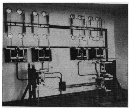 |
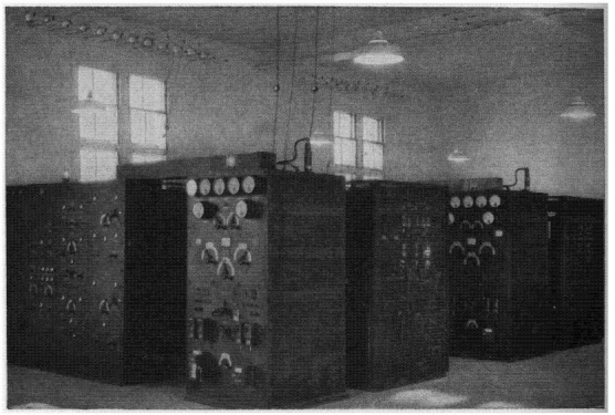
| FIG. 4.93. Contactor switching system for a 50-kilowatt high-frequency broadcasting station at Rio de Janeiro, showing the branching circuits from one transmitter to eight two-wire balanced transmission lines feeding separate antennas. The contactors are low-capacitance double-pole double-throw devices designed for radio-frequency service. Balanced static drain coils, center-grounded, are associated with each feeder. (Photograph courtesy of Radio National, Rio de Janeiro and RCA International Division.) |
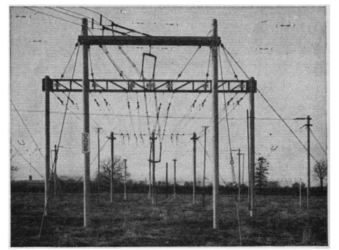 |
| FIG. 4.94. A system of feeder and phasing sections associated with a slewable reversa-ble dipole array with reflector curtain, for 100-kilowatt operation in the high-frequency broadcast service of the British Broadcasting Corporation. The photograph illustrates various assembly and rigging details, steel-post utilization, the use of cages of conductors to maintain uniform characteristic impedances, and the use of four-wire balanced side-connected feeders. A portion of the dipole array is seen in the background. Switching is accomplished manually, moving the flexible cage section to three positions. (Photograph by British Broadcasting Corporation and reproduced by courtesy of Institution of Electrical Engineers.) |
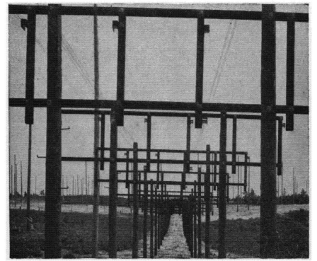 |
| FIG. 4.95. Line construction for supporting several feeders of the four-wire cross-connected balanced type as used at the Riverhead receiving station for connecting diversity high-frequency receiving antennas with the diversity receivers. Note the small cross section of each feeder and the large separation between feeders to obtain very low line pickup and cross talk. RCA fishbone-antenna arrays are in the background. (Photograph courtesy of RCA Communications, Inc.)
|
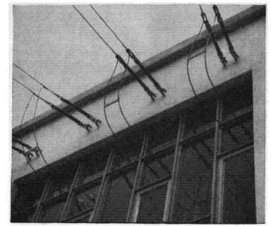 |
| FIG. 4.96. Building entrance detail for several two-wire balanced feeders. (Photograph courtesy of Canadian Broadcasting Corporation.) |
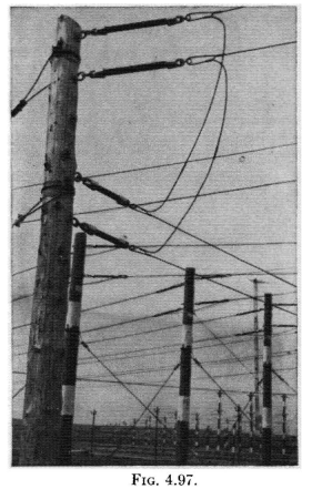 |
| FIG. 4.97. Turning a corner and changing the height of a two-wire balanced feeder and maintaining constant wire lengths in each side of the circuit. Shown against a background of feeders used at the Canadian Broadcasting Corporation high-power high-frequency broadcasting station at Sackville, New Brunswick. (Photograph courtesy of Canadian Broadcasting Corporation.)
|
 |
| FIG. 4.98. Double-strain pole in a two-wire balanced feeder system. (Photograph courtesy of Canadian Broadcasting Corporation.) |
 |
| FIG. 4.100. A right-angle bend in a balanced two-wire feeder, made so as to maintain constant length in the wires on each side of the circuit. (Photograph courtesy of Canadian Broadcasting Corporation.) |
 |
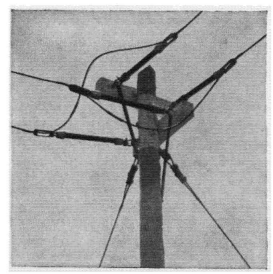
| FIG. 4.99. Corner pole in a two-wire balanced feeder system with the feeder plane turned so as to make the turn with the same length of wire in each side of t he circuit. (Photograph courtesy of Canadian Broadcasting Corporation.) |
 |
| FIG. 4.101. Detail of a double-strain pole in a balanced two-wire feeder. (Photograph courtesy of Canadian Broadcasting Corporation.) |
 |
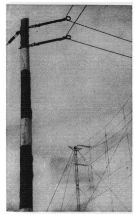
| FIG. 4.102. Detail of a parallel-wave drain on a two-wire balanced feeder system, consisting of a quarter-wave balanced stub across the feeder, the end of which is connected to ground with a single conductor one-quarter wavelength long. (Photograph courtesy of Canadian Broadcasting Corporation.)
|
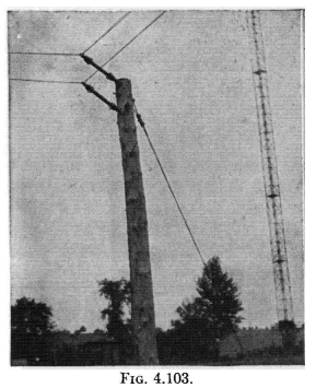 |
| FIG. 4.103. Corner pole in a two-wire balanced feeder. (Photograph courtesy of Royal Canadian Navy.) |
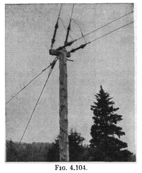 |
| FIG. 4.104. End pole in a two-wire balanced feeder, where it rises to the antenna. (Photograph courtesy of Royal Canadian Navy.) |
 |
| FIG. 4.105. Ceramic insulator crossarm used for two-wire balanced lines. (Photo-graph courtesy of Wind Turbine Company.) |
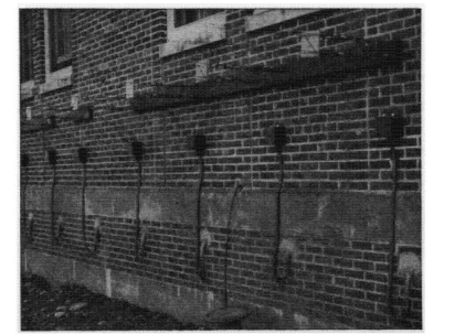 |
| FIG. 4.106. Detail showing the feeders for a receiving installation using four-wire cross-connected open-wire feeders terminating at a building and entering through coaxial feeders. The wide-band high-frequency balance to unbalance transformers are in the weatherproof black boxes on the building. (Photograph courtesy of Royal Canadian Navy.) |
 |
| 4.107. Several feeders of the three-wire type V (two outer wires grounded) with 235-ohm impedance for inside connections to directive-antenna tuning and phasing equipment. (Photograph courtesy of RCA Victor Company, Ltd., Montreal.) |
|
 Radio-frequency Transmission Lines


