| Radio Antenna Engineering is a free introductory textbook on radio antennas and their applications. See the editorial for more information.... |

|
Home  Radio-frequency Transmission Lines Impedance-matching Techniques Parallel Stub Lines for Impedance Matching Radio-frequency Transmission Lines Impedance-matching Techniques Parallel Stub Lines for Impedance Matching |
||||


|
  |
|||
|
Parallel Stub Lines for Impedance MatchingAuthor: Edmund A. Laport
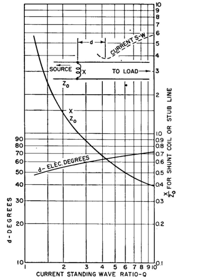
The circle diagram (Fig. 4.58) may also be read in terms of conductance and susceptance in the same way it was previously used for resistance and reactance, reading conductance in mhos instead of resistance in ohms and susceptance in mhos instead of reactance in ohms. A stub line that is short-circuited is more easily adjusted than one open-circuited, and is for that reason the commonly preferred type. When its length βl < 90 degrees, the stub is inductively reactive and therefore has positive susceptance. A point on the feeder can always be found where the susceptance is negative and therefore requires a stub of positive susceptance to neutralize it.
Such a stub is designed from the equations
When the stub line has the same characteristic impedance as the feeder, Fig. 4.37 can be used to read directly the location and length of both open-circuited and short-circuited stubs for a correct impedance match.
|
||||
| Home Radio-frequency Transmission Lines Impedance-matching Techniques Parallel Stub Lines for Impedance Matching |
|
|||
Last Update: 2011-03-19