| Radio Antenna Engineering is a free introductory textbook on radio antennas and their applications. See the editorial for more information.... |

|
Home  Radio-frequency Transmission Lines Impedance-matching Techniques Impedance Matching with an Inductor or Capacitor Radio-frequency Transmission Lines Impedance-matching Techniques Impedance Matching with an Inductor or Capacitor |
||||


|
  |
|||
|
Impedance Matching with an Inductor or CapacitorAuthor: Edmund A. Laport In this case the procedure is identical to that for a stub, except that an inductor or a capacitor of proper value is bridged across the feeder at the proper point to effect the match. The use of an inductor or a capacitor is much more convenient and economical than a stub line and is therefore frequently preferable to a stub. Figures 4.38 and 4.39 are for use with shunt coils.
Figure 4.38 shows the location and relative reactance of a shunt coil that will match a feeder for standing-wave ratios up to 10. These were derived from the circle diagram (Fig. 4.58) in the following way:
In following the Q circles around clockwise to the vertical dashed line through the focal point, an electrical length βl is also read from the chart at this intersection. The distance from a current minimum to the matching point must be the complement of the angle read from the chart. If βl is the value read from the chart, the electrical distance βl0 to use will be 90-βl. Since it is equally important to use the chart (Fig. 4.58) in both impedance and admittance forms, one should become thoroughly familiar with both procedures. To illustrate its use in admittance form, consider the following problem:
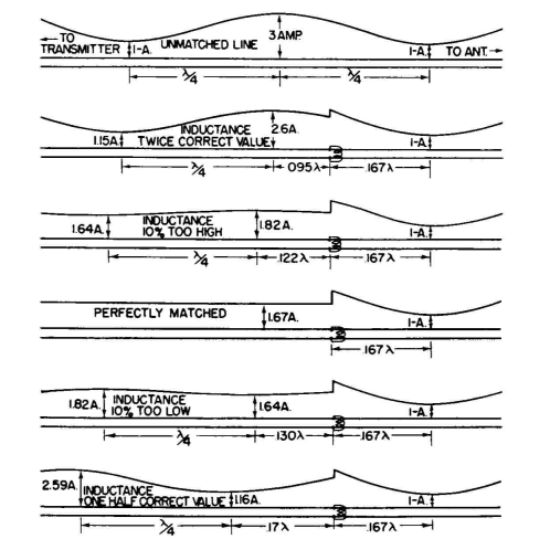
Assume that a 500-ohm feeder has been measured and found to have a standing-wave ratio of 3.0 and that the location of a current minimum has been marked for reference. We wish to match this feeder by using a shunt coil, and we must determine where to place this coil and also its reactance. From the chart, we locate the intersection of the circle for Q = 3.0 and the vertical dashed line through the focal point 1+j0 and read a susceptance of -j1.15. This occurs on the curvilinear radial line corresponding to βl = d = 30 degrees. Since we must take the complement of 30 degrees in this case, the proper distance of the coil from the current minimum will be d0 = 90-30 = 60 degrees, or 0.167 wavelength. The relative susceptance of the line is -j1.15, and so the relative reactance will be 1/-j1.15 = -j0.87. These values are now multiplied by the value Z0 = 500 ohms to obtain true working values. At this point, the line appears as a resistance of 500 ohms in parallel with a capacitive reactance of 500 It is instructive to prove this in the following way: At a current minimum, the impedance of the line in the direction of the load is identical to a termination in a resistance
The location of the matching coil was found to be 60 degrees toward the generator from the current minimum. These values can be inserted in Eq. (8) (page 368), from which it is computed that the impedance of the line looking in the direction of the load is 215-j248 ohms. To transform this impedance to a matching value of 500 ohms resistance, it is found that the inductive reactance required is 435 ohms, connected in parallel with the line. In this discussion we have used the lower half of the chart, where the susceptance was negative, so that we could perform the match with an inductance. Had we taken the conjugate point in the upper half of the chart, where the susceptance of the line is positive, we should find that the match can be effected in the same way if a capacitor of the correct value is bridged across the line. However, the reversal of the direction in the chart necessitates a reversal in the direction of the matching element from the current minimum, which would be toward the load instead of toward the generator. Figure 4.38 can also be used to determine the location of an inductive parallel stub line. When a parallel stub is used for matching, its reactance at correct match will be identical to that of a parallel coil. When the characteristic impedance of the stub line is the same as that of the main feeder, its length and location can be read from Fig. 4.37 directly. When the stub has a different characteristic impedance, the required relative reactance is taken from Fig. 4.38, and Eq. (11) is solved for the length βl of the stub, using the value chosen for its characteristic impedance. Figure 4.39 is a pictorial indication of the effect of varying the value of the reactance of a shunt impedance-matching coil that is correctly located on the feeder to obtain a match. Figure 4.40 represents another way in which a feeder can be matched by using reactive elements in series with the line, using the correct value at the correct location. Its application is exemplified by the following:
A 600-ohm feeder is found by measurement to have a standing-wave ratio of 1.8, and the location of the current minimum nearest to the load has been marked. Figure 4.58, used in its impedance form, is now applied in exactly the same manner as explained for use in its admittance form. The Q circle for 1.8 (interpolated) is followed clockwise until it intercepts the vertical dashed line through the focal point, at which point the resistance component of the series impedance of the line at that point (37 degrees toward the transmitter from the current minimum) is equal to Z0. The normalized series component of reactance at that point, read from the chart, is -j0.60. If a series inductor of normalized reactance j0.60 is placed in series with the line to neutralize the line reactance, the line is matched. In this case the value required is 0.60 Since the circuit is balanced, coils of one-half this value are placed in each side of the line, as in Fig. 4.40A. Following the Q circle counterclockwise to obtain the conjugate matching point, and measuring the distance to the matching point in the opposite direction from the current minimum, the same result can be realized with capacitive reactance of the same value, as represented in Fig. 4.40B. Figure 4.40C represents the use of series stubs to obtain the same effects.
|
||||
| Home Radio-frequency Transmission Lines Impedance-matching Techniques Impedance Matching with an Inductor or Capacitor |
|
|||
 0.87 = 435 ohms. If an inductance of 435 ohms is bridged across the line at this point, their joint reactances go to infinity, leaving the real value of 500 ohms. The line is then matched.
Last Update: 2011-03-19