| Radio Antenna Engineering is a free introductory textbook on radio antennas and their applications. See the editorial for more information.... |

|
Home  Radio-frequency Transmission Lines Network Equivalents of Transmission-line Sections Radio-frequency Transmission Lines Network Equivalents of Transmission-line Sections |
||||


|
  |
|||
|
Network Equivalents of Transmission-line SectionsAuthor: Edmund A. Laport
Occasionally it is necessary to use a building-out network to serve as the equivalent of a certain short length of line, having a given phase lag and characteristic impedance. Figure 4.44A shows a T network, and Fig. 4.44B shows a π network suitable for producing the equivalent of a section of line less than 180 degrees long.
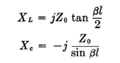
Practically, it is best to use two cascaded sections when the desired length exceeds 120 degrees, in order to avoid excessive potentials and currents in the elements, Considering Fig. 4.44A, the following equations can be used to determine the reactances of the elements;
For the π network of Fig. 4.44B the following equations apply:
If a balanced network is required, the unbalanced solution is used but the series reactances are divided in half and distributed symmetrically in the two sides of the circuit. Any number of sections can be cascaded to obtain, progressively, any desired electrical length, with any desired phase shift per section that is less than 180 degrees. Good engineering design is that which does not lead to impractical reactance values.
|
||||
| Home Radio-frequency Transmission Lines Network Equivalents of Transmission-line Sections |
|
|||


Last Update: 2011-03-19