| Radio Antenna Engineering is a free introductory textbook on radio antennas and their applications. See the editorial for more information.... |

|
Home  Radio-frequency Transmission Lines Balanced to Unbalanced Transformations Radio-frequency Transmission Lines Balanced to Unbalanced Transformations |
||||||||||||||||


|
  |
|||||||||||||||
|
Balanced to Unbalanced TransformationsAuthor: Edmund A. Laport
 , some with coaxial lines and some with open-wire lines. Only a few of the more useful methods are included here. , some with coaxial lines and some with open-wire lines. Only a few of the more useful methods are included here.
Using networks of lumped reactances one can always use a single-ended T or a π section to produce a 90-degree advance of phase of current or potential (or both in the case of resistive loads) to go between an unbalanced generator and one end of a balanced load and an equivalent section with equal but opposite-sign corresponding elements to give a phase lag of 90 degrees to go between the same generator and the opposite end of the balanced load. These two networks together provide a balanced potential across the load, and the phase of the source is 90 degrees with respect to the currents or potentials across the load (see Figs. 5.39 to 5.41 and Fig. 5.42).
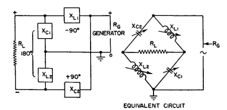
The same result can be obtained by using any arbitrary phase shift θi in one side for phase advancing and a phase shift θ2 of 180 -θ1 in the phase-lagging network. When the impedance transformation ratio is the same in both sides, balanced potentials are produced across the load, while the relative phase of the source is at an angle θ1. There are very few applications where there is need to control the phase differences between the load and the source, so the 90-90-degree method is the most convenient to use. The most usual application is from a resistive load to a resistive source. In a 90-degree network, all three elements of a T or a π have equal reactances. The simplest network of this type is one using four equal reactances, two capacitive and two inductive, in a bridge circuit as shown in Fig. 4.45. This is equivalent to the preceding application of plus and minus 90-degree shifts in the two branches, using L networks. Adjustment for perfect balance can be obtained easily. The network is readily adjustable over a band of frequencies by using identical variable capacitors on a common actuating shaft, and the same with the inductors. The inductors are set to some value and the capacitors tuned until they have the same reactance as that of the inductors. At any given frequency, the transformation ratio of the network can be made anything desired by the choice of the reactances at balance of the bridge. The adjustment for equal capacitive and inductive reactances can be made in two ways: (1) open the balanced resistive load, energize the single-end input at the desired frequency, and tune until the network looks like a short circuit (series resonance) across the source; or (2) short-circuit the balanced resistive load, and tune the network for antiresonance.
This network provides a very simple and versatile balanced-to-unbalanced resistance-to-resistance coupling network that can be used to transform in either direction. The transformation ratio varies with the ratio X/RG. When
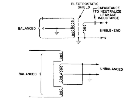
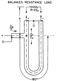
The ratio between the coupled balanced and unbalanced resistances is determined by the turns ratio of the transformer and by the coupling factor. A radio-frequency air-core transformer of this type with a bandwidth of one or two octaves is relatively easy to construct. As the desired band-width is increased to several octaves, the design problem increases rapidly. Toroidal windings on iron-dust cores become useful for wideband designs. Balanced to unbalanced transformers for use with receiving systems have been successfully developed for a band of 8 1/2 octaves. Balance to unbalance networks can be used in one form or another for radio frequencies up to approximately 50 megacycles without serious design problems. The transformers are principally useful for low-energy applications such as receiving circuits but are inconvenient or impractical for most transmitting applications. At the higher frequencies, however, it is often preferred for reasons of cost, simplicity, and convenience to use distributed circuits for balance to unbalance transformations. Where coaxial lines are used, there are certain techniques that have proved very convenient. Figure 4.47 is one circuit often used to transform reversibly between balanced and unbalanced systems. In one direction of working, a single-end source is branched into two lines of equal characteristic impedance, one branch having an electrical length X between the branch and one side of the circuit, while the other has a length X + 180 degrees between the branch and the other side of the balanced circuit. When both branches are terminated in their characteristic impedance, the 180-degree lag in one branch produces the desired inversion of phase to yield balanced potentials across the balanced circuit.
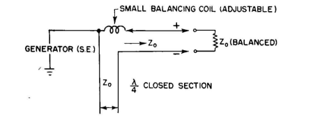
Figure 4.48 is a schematic diagram of the well-known "bazooka," or balun. The outer end is an open double-concentric section 90 electrical degrees long, connected to the sheath of the main feeder one-quarter wavelength from the outer end. The balanced terminals are the innermost conductor and the sheath of the main feeder opposite it. It is not essential that the velocity of propagation in the two parts of the bazooka be identical, and of course the electrical lengths of the system are based on the velocity in the outer coaxial portion.
This is implied in all the foregoing descriptions and in all subsequent ones relating to feeders in which the velocity of propagation is less than that for free-space waves of the same frequency. Referring now to balance to unbalance transformers in open-wire systems, there are relatively few good choices. Figure 4.49 is one example where the equivalent of a closed quarter-wave stub is placed in series with one side of the branch to provide a phase lag of 180 degrees across the terminals of this section.
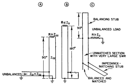
Experience has shown that this is sometimes insufficient by itself to make an exact transformation, but by placing a small inductor in series with the straight portion of the balanced side of the branch it can be adjusted to bring an exact balance at the balanced terminals. Figure 4.50 shows a method that is applicable when substantial standing waves exist on the balanced part of the system. In A, when the load resistance on the balanced side is very much greater than the characteristic impedance of this balanced line, the latter should have a length of 90 degrees, with its lower end grounded. An unbalanced system can now be coupled to this by tapping up from ground on one side of the balanced feeder until the two systems are mutually matched. When the balanced load resistance is much less than the characteristic impedance of the balanced line (B), the same scheme can be used, but with a 180-degree line between the load and the ground. To deliver rated power from a balanced system to an unbalanced load of very high resistive impedance, such as an end-fed dipole, a very high voltage is required.
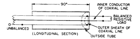
Very large standing waves on an open-ended feeder will develop a potential many times that in the matched portion of the feeder. When a high-resistance load is connected between one end of this feeder and ground, it introduces an unbalance in the system which usually is intolerable. Balance can be restored to such a system by connecting a balancing quarter-wave stub, short-circuited at its outer end, in parallel with the end of the balanced feeder. This system is shown in Fig. 4.50C. The device shown in Fig. 4.51 has been much used in the ultrahigh-frequency region and can sometimes be used in the range of 4 to 30 megacycles without becoming excessively cumbersome. Its simplicity is its principal merit. The outer conductor has two diametrically opposite longitudinal slots cut for a distance of one-quarter wavelength back from the end which is connected to the balanced load (or generator), and the inner conductor is connected to one half of the outer. The other end is the unbalanced terminal. With uniform characteristic impedance throughout its entire length, the transformation ratio is from Z0 (unbalanced) to 4Z0 (balanced). This transformation ratio can be changed by using a different characteristic impedance for that portion of the line which is slotted. For the lengths that would be used for high-frequency applications, the mechanics are impractical unless rigid tubular line is used. The large-diameter lines that are employed in high-power systems are suited to this purpose. The device is adjustable to different higher frequencies by short-circuiting the slots at various points along their lengths. The slot must withstand a potential twice that existing on the full concentric portion of the line when the impedances are matched.
|
||||||||||||||||
| Home Radio-frequency Transmission Lines Balanced to Unbalanced Transformations |
|
|||||||||||||||


Last Update: 2011-03-19