| Radio Antenna Engineering is a free introductory textbook on radio antennas and their applications. See the editorial for more information.... |

|
Home  Radio-frequency Transmission Lines Standing Waves on Open-wire Transmission Lines Radio-frequency Transmission Lines Standing Waves on Open-wire Transmission Lines |
||||||||||||||||||||||


|
  |
|||||||||||||||||||||
|
Standing Waves on Open-wire Transmission LinesAuthor: Edmund A. Laport
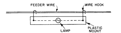
It is quite sufficient in some cases to determine qualitatively that a feeder is terminated approximately correctly.
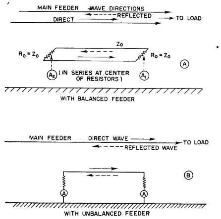
The same method may be used with a thermocouple milliammeter in place of the lamp, provided that the added capacity on one side of the circuit does not in itself cause unbalance. A dummy device or another similar instrument can be hung on the opposite side to reduce unbalance. The limiting parasitic effect then is if the devices have low enough capacitance not to constitute an irregularity in the line and therefore a source of reflections. The milliammeter will reveal effects not observable with the lamp indicator, but its use requires greater care. This device is only an indicator because it responds not solely to current in the line but also to the potential. It is satisfactory for use for the same rough purposes as the lamp indicator. The use of these indicators is the same on unbalanced lines, and the measurements may be made on a ground wire or on a high-potential wire. Neon and argon lamps are very rough indicators of potential distribution, so rough in fact as to have relatively small value for determining the true condition of a line. Indicating devices of the nature of voltmeters bridging a line must be used with extreme caution. Unless the impedance of the device is very large with respect to the line impedance at the points of maximum potential, the voltmeter device itself causes reflections, the magnitude of which varies with position on the line. The result is that a plot of the measured voltage tends to be abnormal. Voltmeter-type indicating or measuring devices are easier to use on low-impedance lines. A method of detecting and indicating the magnitude of standing waves in an open-wire feeder is that shown in Fig. 4.62. A short section of line is placed in the field of the feeder to be studied and parallel to it. This secondary lino is then terminated in its characteristic impedance at both ends and an ammeter placed in series with and at the middle of each terminal resistor. If the main feeder is correctly terminated in its characteristic impedance, there will be a wave traveling in one direction only. The coupled line (reflectometer) then has induced in it a wave traveling in the same direction; and since it is also terminated, this energy will be absorbed in its terminal resistance at one end and there will not be any reflection.
This causes the current at the far end of the secondary line to register on the ammeter there. The near-end ammeter will show zero current. When there are standing waves on the main feeder, there are traveling waves passing in both directions. The one traveling toward the load will actuate the far-end ammeter in the secondary line as before. The wave traveling from the load toward the generator will act in the same manner to actuate the near-end ammeter in the secondary line. The ratio of the two currents at the terminals of the secondary gives a direct measure of the ratio of the magnitudes of the forward and backward waves in the main feeder, which is a measure of the standing-wave ratio. This method does not provide any information concerning the locations of the maximums and minimums on the main feeder, but it is very useful as a permanently installed device to indicate the existence and magnitude of standing waves during station operation. The ammeters can be remote-reading and located in a convenient place to be observed. Like all standing-wave detectors, it may also be calibrated to read power directly as a wattmeter. This principle is applicable to both balanced (Fig. 4.62A) and unbalanced feeders (Fig. 4.62B). In order not to introduce irregularities upon the main circuit, the coupling of the secondary line should be small and sensitive current-measuring instruments used.
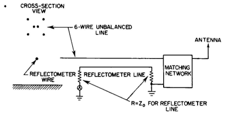
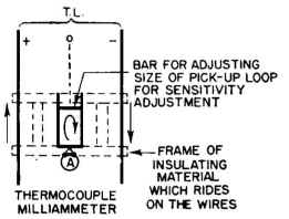
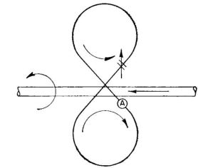
When this device is used only for indicating the presence or absence of standing waves in the main feeder, only one ammeter need be used - the one on the generator end of the secondary line. This ammeter will register current only when there is a standing wave. It is possible to precalibrate this one ammeter in terms of standing-wave ratio, using the second ammeter in the load end during the calibration and then removing it. This standing-wave indicator can be placed anywhere in the system but will usually be wanted near the transmitter, where it can be easily observed by the operating personnel. This method of measuring or indicating standing waves is especially valuable where a feeder must be matched but where there are no measuring instruments available except a thermogalvanometer or a thermo-milliammeter. A coupled line is constructed, its characteristic impedance is calculated, and it is terminated in resistances at each end equal to the characteristic impedance of the reflectometer line. When this is done with unbalanced feeders, as in Fig. 4.62B, care must be taken to include the resistance of the ground terminal in the matching resistances. Since the load-end termination of the reflectometer is most critical, it can be connected as shown in Fig. 4.63, where the actual ground resistance is not involved at that end and a known resistance can be used. With the indicating instrument in the transmitter end of the reflectometer line, terminal adjustments may be made. It is possible to determine the correct adjustment of the matching network when the antenna impedance and the line impedance are unknowns. The use of the ammeter in this way is much more convenient than using it as a means for exploring the standing waves on the feeder and adjusting for eventual uniform current distribution. The reflectometer-line method provides an immediate indication of standing waves and the magnitude relative to a previous condition. The adjusting process is continued until the instrument reads zero. This is one of the simplest methods that can be used conveniently for accurate matching. For accurate measurements of standing-wave patterns the measuring device should be so designed as to be responsive solely to the current in the line or to the potential, but not both. Figure 4.64 shows a common form of sliding thermocouple-milliammeter circuit that is responsive wholly to the magnetic field of the line and therefore accurately indicates the current distribution without introducing additional reflections in the balanced line. The sensitivity of the device is adjustable by adjusting the length of the pickup loop by means of the short-circuiting bar. The device must be symmetrically located between the two sides of the circuit and can be in the form of a frame of insulating material that has grooves spaced so that it slides along the wires, always retaining its exact location between the sides of the feeder. There is no response in this type of device to currents that may be flowing in parallel on the two sides of the circuit. In some instances, the milliammeter loop may be tuned with a series condenser in the middle of the short-circuiting bar. Figure 4.65 is a current-indicating device that is responsive only to the currents on one side of a balanced circuit and is therefore one of the most versatile instruments for open-wire transmission-line measurements. When calibrated against a known current flowing in a straight wire, it can provide absolute measurements of the current in a wire with adequate accuracy for practical field use. It should be constructed on a framework of insulating material which can be set on a wire with constant coupling to the field of the wire and of the sort that has a long handle to facilitate rapid hanging on a wire and carrying along a line.
The current transformer must be symmetrical in the two halves, to eliminate response to the electric field of the wire, and small enough to represent the field of just one wire. With this instrument a complete examination can be made of the magnitude and distribution of currents on each wire of a feeder system.
Currents in a feeder can always be measured directly by inserting matched ammeters in series with the line. When a feeder is exactly matched, ammeters at both ends provide the data necessary to determine the attenuation of the line according to the relation Decibels attenuation =
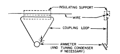
The following sliding-ammeter method is useful for measuring current distributions in antennas and open-wire transmission lines. A suitable radio-frequency ammeter or milliammeter is coupled to the wire with a current transformer consisting of a single-turn loop of rigid wire that is in the form of an equilateral triangle. One side of the triangle is parallel to the wire to be measured and spaced from it a small amount, using an insulated mounting that ensures constant spacing for any position along the wire (see Fig. 4.66).
The ammeter is connected at the apex of the triangle opposite the side coupled to the wire. This device can then be slid along the wire and the relative current distribution observed for all positions. If the sensitivity is insufficient, the reactance of the loop can be tuned out with a series capacitor. If other parallel wires are nearby, as in a multiwire transmission line, the coupling loop for the current transformer must be small with respect to the wire spacing so that the ammeter responds principally to the current in the one wire under observation. The amount of power that must be transmitted to obtain readable values depends upon the size of the coupling loop, whether or not the loop is tuned, and the sensitivity of the ammeter.
At the very high frequencies, where coaxial feeders are almost universally used, impedances are measured by the standing-wave method with extreme accuracy, using a precision-built slotted section of line with the same characteristic impedance as that of the feeder in use, and probing the field of this slotted line with a voltmeter-type indicator. When the position and ratio of a standing-wave pattern have been measured precisely and the exact characteristic impedance is known, the impedance terminating the line can be quickly read from a circle diagram like that of Fig. 4.58.
|
||||||||||||||||||||||
| Home Radio-frequency Transmission Lines Standing Waves on Open-wire Transmission Lines |
|
|||||||||||||||||||||

Last Update: 2011-03-19