| Radio Antenna Engineering is a free introductory textbook on radio antennas and their applications. See the editorial for more information.... |

|
Home  Radio-frequency Transmission Lines Dissipation Lines Radio-frequency Transmission Lines Dissipation Lines |
||||||||||||||||


|
  |
|||||||||||||||
|
Dissipation LinesAuthor: Edmund A. Laport
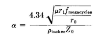
Where the amount of power to be dissipated is small, tapered lines may be an unnecessary complication in design. Then the line simply acts as a resistance when its attenuative length is great enough to eliminate variations of impedance in the input end of the dissipation line at the lowest working frequency. Various other alternatives are available. The total length of the line can be shortened by substituting a fixed resistor of approximately correct value after the line has dissipated all but the last few watts. If the power delivered at the end of the rhombic antenna is small, a fixed resistor of the correct value of resistance and of very high power factor can be located directly at the rhombic-antenna terminals in place of the terminal-line structure. A dissipation line with an over-all attenuation of 20 decibels acts virtually as an infinite line so far as its effect on the rhombic antenna is concerned. The total attenuation of 20 decibels to the transmitted and 20 decibels to the reflected wave being 40 decibels (reduction to 1 percent in voltage), the end of the dissipation line can be open-circuited, short-circuited, or grounded at will without observable influence on the input impedance. A static drain direct to ground is desirable as a protective measure. Satisfactory termination on the same basis can be had for most cases with a dissipation line having an attenuation of 15 decibels. If a resistor is used to consume the last few watts, attenuative lengths of 12 decibels are practical. In such a case, the specifications of the resistor are less rigorous with regard to low reactance than when resistors are used for direct termination of the antenna. When resistors are used to save line length, it is desirable to ground the middle for static draining. The attenuation per unit length is inversely proportional to characteristic impedance when the number and the size of the wires are constant. It is therefore a matter of good design economy to reduce the characteristic impedance of the dissipation line to the lowest value that is mechanically practical without increasing the number of wires. Experience has established the use of stainless-steel wire as the preferred material for a dissipation line. Its high radio-frequency resistance provides a relatively high attenuation factor. It resists corrosion in the weather, and its electrical characteristics are constant in time. Its cost is reasonable. Since attenuation is desired in the dissipation system, the insulation of the line may be lossy and the line can be attached directly to wood supports provided that the temperature is not sufficient to burn them. The characteristic impedance of a line using wire of magnetic material is practically the same as one using nonmagnetic materials. The permeability of the material adds only a small and negligible term in the equation for characteristic impedance. Stainless steel is of many different alloys, which vary widely in resistivity and permeability according to their composition. Alloy 430 (18 percent chromium) has a resistivity forty times that for annealed copper and is magnetic. The attenuation of balanced lines using steel or iron wires of magnetic permeability μ and resistivity r1 can be computed from the following equation;
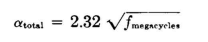
In this equation r0 is the resistivity of copper, which is 1.724·10-6 ohm per cubic centimeter for annealed copper and 1.77·10-6 for hard-drawn copper. This attenuation is for conductor loss only. Figure 4.59 shows attenuations for 0.040-inch-radius steel wire lines in a two-wire balanced 400-ohm circuit. Sterba and Feldman21 have published measurements made on a 600-ohm two-wire balanced line using uncoated iron wires of resistivity 12.3·10-6 ohm-centimeter and permeability of 92, with a wire diameter of 0.162 inch. This line follows the relation
A copper line of the same dimensions follows the relation
whereas the copper loss alone for this same line follows
The dissipation line is usually located under the rhombic antenna with which it is associated because no additional land is required. The line can be turned back and forth so as to use the smallest number of poles.
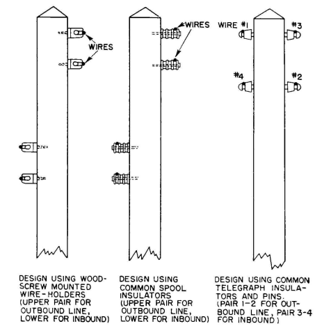
If the characteristic impedance of the dissipation line is quite low, its spacing is small and one short crossarm can readily support the double line obtained when the line is folded back on itself. Bracket insulators may be attached directly to the poles to eliminate crossarms. When this is done, a sufficient distance between the "go" and "return" lines can be obtained by putting one of the runs lower down on the opposite side of the pole, as shown in Fig. 4.60. In certain applications the dissipation line and the feeder can be switched from one end of the rhombic antenna to the other to reverse its directivity. In such cases, the impedance of the ends of the antenna must be equal and brought uniformly to a central switching point for interchanging the power feeder with the dissipation line.
To take advantage of the low characteristic-impedance dissipation line, tapering must then start from the switching position. The same poles can be utilized to carry the transmission line and to support the dissipation line. Reference to the attenuation formulas for transmission lines types I, II, and III reveals that such lines may also serve as dissipation lines, using the earth as the dissipator. A balanced dissipation line made up of two unbalanced lines of these types is practical and may often be used advantageously, especially for the lower impedances, the higher high frequencies, and the poorer ground conductivities. By studying the possibilities of such applications by setting the relevant values in the attenuation equations, it will often be found that copper lines using ground dissipation have more unit-length attenuation than lines of dis-sipative conductors that do not use ground loss. In a limited number of cases the most economical dissipation line may be one using both conductor and ground dissipation. The empirical nature of these possibilities makes the choice dependent upon the particular circumstances surrounding each application. Lines using ground dissipation require a few simple precautions to ensure stable characteristics as the ground conductivity changes with weather conditions. The input end of the line may require some limited form of ground system which gradually spreads out and disappears in the first decibel or two of line length, after which the effect of varying ground conductivity is relatively unimportant in its effect on the input impedance. The height above ground is an important factor in the design of ground dissipation lines. An example of the possibilities of using two unbalanced 175-ohm dissipation lines to terminate a 350-ohm balanced system is the following: The measured values of characteristic impedance and attenuation on a line 300 feet long comprising four parallel copper wires of radius 0.050 inch spaced 20 inches in a horizontal plane 60 inches over ground with a conductivity of about 2·10-13 electromagnetic unit were
|
||||||||||||||||
| Home Radio-frequency Transmission Lines Dissipation Lines |
|
|||||||||||||||


Last Update: 2011-03-19