|
Wire Stringing
Author: Edmund A. Laport
The tensile strengths of hard-drawn copper
and copper-clad steel wires are given in many handbooks and commercial catalogues.
 |
| FIG. 4.77. Arrangement of pressurized coaxial feeders from the transmitter building to six radiators of the directive-antenna system for Station KTBS. (Photograph courtesy of W. M. Witty.) |
The relations between span, sag (or dip), wire size, and tension are given in the following equation,
in which S is the sag in feet, W the weight of the wire in the span, L the span length in feet, and T the tension in pounds.
The stringing of the wires must take into account the temperature at the time of stringing and also the minimum temperature to which the system will be exposed. In a system that is not counterweighted to retain a constant tension, the contraction of the wire at minimum temperature, together with wind and ice loadings, must not stress the wire beyond the ratio of its ultimate breaking strength and the designer's factor of safety. The weight of ice and the effective weight of the wind loadings are added to W in the above equation, and the maximum expected displacement is computed for this extreme condition. A factor of safety of from 2 to 3 is usually adequate for this purpose. In stringing
the wire in calm weather at some higher temperature, the extreme condition can be approximately simulated by dividing the total calculated weight of ice and wind load into four equal static loads and attaching them to the wire at points of approximately equal distance between the two poles of a span. The sag is adjusted then to be about 10 percent more than that computed for the extreme condition to allow for the effect of contraction. Sag can be measured with a transit. Another way is to compute the sag as before for the extreme condition and then string the unloaded wire for this same sag.
´
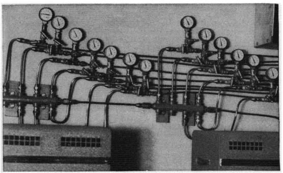 |
| FIG. 4.78. Details showing pressure gages for the dehydrated-air-distribution system for the coaxial feeders of Fig. 4.77 at Station KTBS. (Photograph courtesy of W. M. Witty.)
|
The tension of the wire loaded only by its own weight can then be calculated from the same equation. This tension can then be measured with a dynamometer during stringing or by timing the natural period of vibration of the wire and applying the following equation, 
in which T is the tension in pounds as derived from the previous equation and t is the time in seconds for N complete fundamental vibrations of the whole span.
This measurement is made as follows: Snap the wire at its mid-point by pulling it to one side and releasing it. At the moment of release a stop
watch is started, and the number of complete swings of the wire are counted (say 10 vibrations), at which moment the watch is stopped. Applying this information to the foregoing equation gives its tension.
Most wires when stressed appreciably will stretch slightly. This stretch is a partial allowance for contraction at lower temperatures.
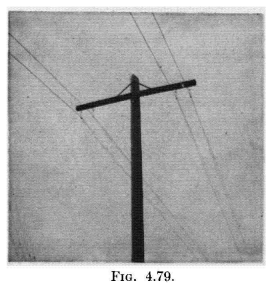 |
| FIG. 4.79. Two-wire balanced feeders, using the crossarm suspension type of construction. |
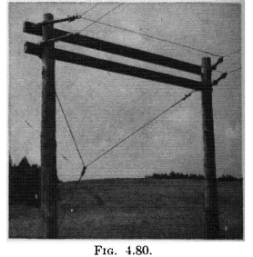 |
| FIG. 4.80. Double-vertical bend at the mid-point of a two-wire balanced dissipation line where the direction of the line is reversed. (Photograph courtesy of Royal Canadian Navy.) |
Guy wires can be correctly stressed using the same formulas. There are three classes of loading used to design pole lines, designated as shown in Table 4.5.
| TABLE 4.5. WIRE LOADINGS |
| Loading |
Wind pressure, pounds per square feet, on projected areas |
Temperature (minimum) (degrees Fahrenheit) |
Radius of ice (inches) |
|
Light
|
12
|
30
|
0
|
|
Medium
|
8
|
15
|
1/4
|
|
Heavy
|
8
|
0
|
1/2
|
|

 Radio-frequency Transmission Lines


