| Radio Antenna Engineering is a free introductory textbook on radio antennas and their applications. See the editorial for more information.... |

|
Home  Impedance-matching Networks Type III Problem Impedance-matching Networks Type III Problem |
||||||||||||||||||||||


|
  |
|||||||||||||||||||||
|
Type III ProblemAuthor: Edmund A. Laport
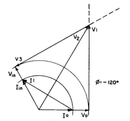
Procedure. Write the problem vectorially as shown in Fig. 5.25. Because input impedance equals the load impedance, the input is represented by vectors of the same length as for the load, but with the specified phase difference. Then, if we chose a T network (Fig. 5.26), we erect perpendiculars through V0 and Vin and connect I0 with Iin as shown in Fig. 5.27. From this we obtain the solution shown in Fig. 5.28.
Had we chosen the π solution, the vector diagram would have been as shown in Fig. 5.29. A reversal of the phase angle in any problem reverses the signs of all the elements. For instance, in this problem, if the phase angle had been + 120 degrees, all elements would change from L to C, and vice versa, maintaining the same numerical values. A phase-shifting network of this type is equivalent to a section of an infinite transmission line having a characteristic impedance R0 and an electrical length equal to that of the angle of phase shift, which in such cases must be negative. This provides a handy device to study certain properties of lines, such as the 45 degree and the 90 degree sections which have special properties.
For example, how does the input impedance of a 45 degree section of a transmission line change with variation of the terminal resistance from 0 to
The limiting conditions are quickly examined by assuming open-circuit and short-circuit terminal conditions. For the former, Zin is the sum of j0.42 and -j1.42, which is -j1.00. For the latter, the solution for Zin yields +j1.00. So we easily find that Zin remains constant in magnitude for all conditions of resistance termination but varies in character from pure capacitive reactance, through pure resistance to pure inductive
reactance as the terminal resistance varies from
Proceeding in the same manner, the 90-degree network is analyzed.
Its special property of impedance inversion is worthy of digression to see why it works as it does. The vector diagram for a -90-degree T network with a characteristic impedance R0 is given in Fig. 5.32. From this we find the equivalent circuit elements, in terms of R0 , to be those of Fig. 5.33. All the elements of the network have reactances equal in magnitude to R0 .
At this point we can test the circuit for open- and short-circuit terminal conditions and see what happens to Zin. When Rt = R0 , Zin = R0 . When Rt = 0, X1 and X2 in parallel give a condition of anti-resonance and Zin =
|
||||||||||||||||||||||
| Home Impedance-matching Networks Type III Problem |
|
|||||||||||||||||||||


 ? Solve for the equivalent single-stage network having a characteristic impedance R0 when it is terminated in a resistance R0 by assuming it to be a -45 degree phase-shifting network. (We illustrate with the T network.) The vector diagram is shown in Fig. 5.30. Thus, taking R0 as unity, we obtain the ratio of all other elements to R0 . We can then assume any value of terminal resistance and calculate the resulting input impedance. We obtain the circuit of Fig. 5.31.


Last Update: 2011-03-19