| Radio Antenna Engineering is a free introductory textbook on radio antennas and their applications. See the editorial for more information.... |

|
Home  Impedance-matching Networks Type II Problem Impedance-matching Networks Type II Problem |
|||||||||||||||||||||


|
  |
||||||||||||||||||||
|
Type II ProblemAuthor: Edmund A. Laport
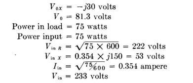
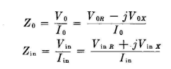
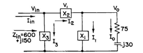
Problem. We desire to couple a load circuit having an impedance of Z0 = 75 - j30 to a circuit which requires a terminating impedance of Zin = 600 + j150. The transformation, let us say, must be made with a phase difference between the load current and the input current of plus 60 degrees. What is the network design required? Procedure. The problem is set up in vector form first, on the basis that power input equals power output. Let Then
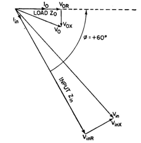
To solve for the network required to make the indicated transformation, complete the vector diagram as shown in Fig. 5.14, and obtain therefrom the nature and magnitude of the required reactances.
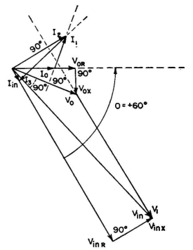
Draw V1 in a direction perpendicular to I0, starting at V0, as shown in Fig. 5.16. Then draw V3 in a direction perpendicular to Iin, through Vin. The intersection of these perpendiculars locates the lengths of V1, V2, and V3. Draw V2 from the origin to the intersection.
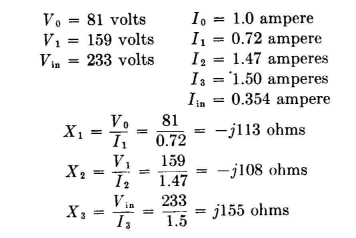
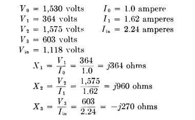
As before, I1 is drawn to connect I0 and Iin. From the scales of Fig. 5.15
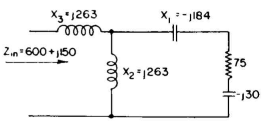
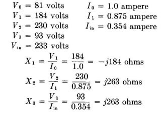
The network becomes that shown in Fig. 5.17. Solving this same problem on the basis of a π network (Fig. 5.18), we construct Fig. 5.19. Tabulating values from vector scales, we obtain
The circuit becomes that of Fig. 5.20.
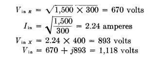
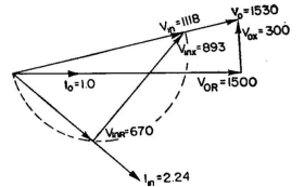
Problem. Calculate the required elements of a network which will make a transformation from 1,500 + j300 (load) to 300 - j400, so that the potential across the load is in phase with the input potential. Procedure. Vector statement of this problem is, after resolving the input and load potentials into their resistive and reactive components on the basis of equality of power at input and output, shown in Fig. 5.21 with the scales chosen (for example, 1 inch = 1.0 ampere and 1 inch = 500 volts).
This shows Vin in phase with V0 as required, and the relative directions of I0 and Iin. It also is marked to show the potentials and currents prevailing in the load and for the input to the network. From this point, the vector diagram must be completed for either a π or a T network. We shall demonstrate both and compare them.
The block diagram of the π network version for this problem is shown in Fig. 5.22. The vector diagram shows that V0 and Vin are in phase. Vectors I1 and I3 must both be perpendicular to the direction of V0 and Vin; thus they can never intersect. A solution with a π network is therefore impossible.
The T network provides a solution for the problem as shown in Fig. 5.23.
The network is shown in Fig. 5.24. NOTE: If the problem had specified that the load and input currents be in phase, then a π solution would be possible and the T solution impossible.
|
|||||||||||||||||||||
| Home Impedance-matching Networks Type II Problem |
|
||||||||||||||||||||


Last Update: 2011-03-19