| Radio Antenna Engineering is a free introductory textbook on radio antennas and their applications. See the editorial for more information.... |

|

Home  Logarithmic-potential Theory Logarithmic-potential Theory  One Wire above Ground One Wire above Ground |
||||||


|
||||||
|
One Wire above GroundAuthor: Edmund A. Laport
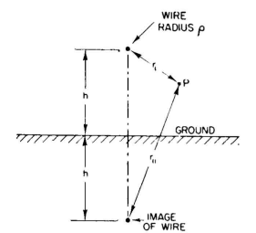
The simplest case to study is that of a single elevated wire parallel to ground (Fig. 6.1). The potential on the wire, in terms of its charge per meter, is written
The induced potential on the wire due to its image is
The total potential on the wire is the sum of these direct and induced potentials.
In taking the ratio the unknown integration constant x is eliminated. The reciprocal capacitance is
The characteristic impedance for this wire is
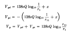
There are many applications where it is necessary to find the potentials in space in the region of a transmission line, and we may wish to locate the equipotential lines. The electric lines of force are everywhere normal to these equipotential lines. From such calculations the potential gradients can be computed. For this single-wire line, the potential at a point P in space in the region of the wire is obtained exactly as before, except that the point at which the potential is calculated, which previously was on the surface of the wire, is now some distance from it. The equations are then written
Then
From this equation the equipotential lines can be completely located and potential gradients found. In the following developments the same general philosophy applies so that at the outset we can omit the integration constant x in writing the potential equations since it will always fall out when we arrive at the point of taking the ratios in which we are primarily interested and from which all the essential information is derived.
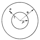
Another application of basic simplicity is the derivation of the characteristic impedance, the capacitance per unit length, and the field distribution for a concentric line (Fig. 6.2). In this case the potential on the inner conductor due to its own charge is, after omitting the integration constant x,
These charges set up a potential at the inside surface of the outer conductor which is
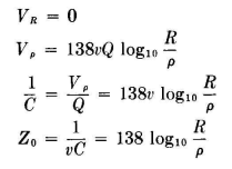
The image charges on the inner surface of the outer conductor set up a field which will reduce the total potential on its surface to zero. This is the same as equating VR to zero. After this step, we proceed as before and obtain Since
At a point P in the dielectric space between conductors, the potential will be the same as if the radius of the inner conductor were increased to the value r1, the distance of the point P from the axis. Therefore we can substitute Vp for Vρ and write
Then
|
||||||
Home  Logarithmic-potential Theory Logarithmic-potential Theory  One Wire above Ground One Wire above Ground |
||||||
Last Update: 2011-03-19


