| Radio Antenna Engineering is a free introductory textbook on radio antennas and their applications. See the editorial for more information.... |

|
Home  Logarithmic-potential Theory Two-wire Balanced Transmission Line Logarithmic-potential Theory Two-wire Balanced Transmission Line |
||||||


|
  |
|||||
|
Two-wire Balanced Transmission LineAuthor: Edmund A. Laport
The wire potentials are always with respect to ground, or zero potential. A balanced two-wire line has two parallel wires of radius ρ, spaced a distance a and located at a height h above ground. The potential between wires is twice that of each wire to ground. The calculation of the capacitance, the characteristic impedance, and the field equipotential surfaces proceeds in this case as follows (see Fig. 6.3):
The potential of wire 1 is written
and for wire 2, V2 = -V1. Then
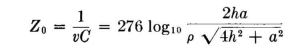
and so When h >> a,
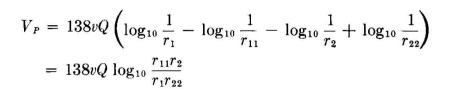
It is evident from this development that when the height is very large with respect to the wire spacing the effect of the presence of ground becomes negligible and the line may be considered to be in free space. The electric field around a balanced line parallel to ground can be completely calculated in the following way: The potential at a point P in space is the sum of the potentials from the two wires and their images. This gives
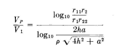
In terms of the potential at the surface of wire 1
When a two-wire balanced transmission line is far enough removed from ground so as to be considered to be in free space, r11 and r22 are eliminated and the field can be plotted from the relation
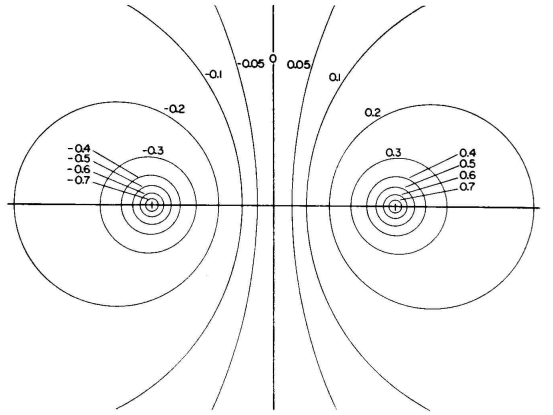
A field map derived from this equation is shown in Fig. 6.4. It is instructive to examine this map to determine what additional information it can yield. The equipotential lines are plotted at intervals corresponding to 10 percent of the wire potentials, which are actually con-focal cylindrical surfaces enclosing the charged wires. As the potential in space approaches zero, the cylinders become larger, until when the potential is zero their radii are infinite. This makes the zero-potential surface a flat plane midway between the wires. The fields each side of this plane are mirror images of each other and have reversed polarities. According to the principles of electrostatics, any equipotential surface in space can be replaced by a coincident metallic surface without disturbing the field in any way. If this metallic surface is closed, and its charge is on the outer surface, the external field is undisturbed but the internal field vanishes.
In this particular case where the equipotential surfaces are cylinders it would be physically practical to substitute a metallic cylinder for those shown in the map. Remembering that C = Q/V and therefore that Z0 = V/vQ, one can read from the map the relative capacitance C00/C0 per unit length and the relative characteristic impedance Z00/Z0 in proportion to the values for which the map was originally plotted, for any combination of two cylindrical conductors lying on the equipotential lines shown. Figure 6.4 was plotted for a 600-ohm balanced transmission line. The contours higher than 0.7 of the wire potential cannot be legibly shown for the scale selected for this figure.
Let a transmission line be formed by conductors lying on the equi-potential surfaces 0.7 and -0.7 of Fig. 6.4. The original conductors forming the 600-ohm line lie on the surfaces 1.0 and -1.0 (not shown), so that their total potential difference is 2.0. For the 0.7 surfaces, the total potential difference becomes 1.4. Since the propagation velocity and the charge per unit length are constant for this map, the characteristic impedance Z00 for the two conductors on the 0.7 surfaces can be found from the relation
The field between these two conductors remains unchanged by this substitution. The field inside each of the two cylindrical conductors vanishes. Next consider a balanced transmission line composed of two cylindrical conductors of unequal radii, one lying on the 0.5 line of Fig. 6.4 and the other on the -0.3 line. The potential difference is now 0.8. For this arrangement
Then consider the eccentric transmission line formed by one cylinder lying on the 0.5 line and the other enclosing it with its inner surface on the 0.2 line. Their potential difference is 0.3, and
The same kind of analysis applied to any equipotential field map will yield similar information, but the equipotential surfaces usually do not have shapes which are easily obtained practically, such as the cylinders which result from this particular map.
|
||||||
| Home Logarithmic-potential Theory Two-wire Balanced Transmission Line |
|
|||||


Last Update: 2011-03-19