| Transistor Basics is a free introductory textbook on transistors and their basic applications. See the editorial for more information.... |

|

Home  The Grounded Base Transistor The Grounded Base Transistor  The Grounded Base Connection The Grounded Base Connection  Input Resistance Input Resistance |
||||||||||||||||||||


|
||||||||||||||||||||
|
Input ResistanceAuthor: Leonard Krugman
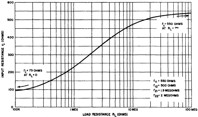
The input resistance of the grounded base transistor shown in Fig. 3-9 can now be computed in terms of the transistor parameters and the transistor four-terminal open-circuit parameters. Since the input resistance as seen by the signal generator is r1, Fig 3-9 may be simplified as shown in Fig. 3-10. This series circuit is expressed Eg = i1(Rg + r1) or
Substituting equation 3-3 for i1
then
and in terms ot the open-circuit parameters
|
||||||||||||||||||||
Home  The Grounded Base Transistor The Grounded Base Transistor  The Grounded Base Connection The Grounded Base Connection  Input Resistance Input Resistance |
||||||||||||||||||||
Last Update: 2010-11-17


