| Transistor Basics is a free introductory textbook on transistors and their basic applications. See the editorial for more information.... |

|

Home  Grounded Emitter and Grounded Collector Transistors Grounded Emitter and Grounded Collector Transistors  The Grounded Emitter Connection The Grounded Emitter Connection  Equivalent Operating Circuit Equivalent Operating Circuit |
|


|
|
|
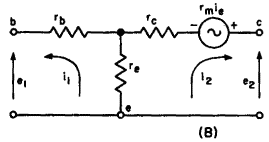
Grounded Emitter ConnectionAuthor: Leonard Krugman The grounded emitter connection is illustrated in Fig. 4-1 (A). In this case the input connection is made between the base and emitter electrodes (conventionally the emitter is shown schematically as an arrowhead resting on the base), and the output is taken between the collector and the emitter. Thus, in this case, the emitter is the common electrode. Figure 4-1 (B) illustrates the equivalent active "T" circuit for the grounded emitter connection.
Fig. 4-1. (A) The grounded emitter connection. (B) Equivalent active "T" for grounded emitter connection.
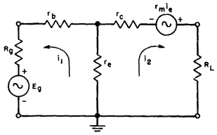
Fig. 4-2. Operating circuit, grounded emitter connection. Figure 4-2 is the complete operating circuit of the grounded emitter connection. Notice that although the negative side of the signal generator is grounded, the polarity of the signal in this connection is reversed with respect to the emitter and base terminals shown in the grounded base connection of Fig. 3-9. Since this effective reversal of input leads is the only physical difference between the two connections, the grounded emitter, unlike the grounded base, produces a phase inversion of the input signal.
|
|
Home  Grounded Emitter and Grounded Collector Transistors Grounded Emitter and Grounded Collector Transistors  The Grounded Emitter Connection The Grounded Emitter Connection  Equivalent Operating Circuit Equivalent Operating Circuit |
|
Last Update: 2007-09-12


