| Transistor Basics is a free introductory textbook on transistors and their basic applications. See the editorial for more information.... |

|

Home  Transistor Amplifiers Transistor Amplifiers  The D-C Operating Point The D-C Operating Point  Hunter-Goodrich Bias Method Hunter-Goodrich Bias Method |
||


|
||
|
Hunter-Goodrich Bias MethodAuthor: Leonard Krugman
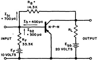
Fig. 5-5. Hunter-Goodrich bias method. As in the preceding cases, the effect of the base and emitter circuit resistances (re + rb) can be neglected in the calculations. The values of RF and EF depend upon the value of fixed bias desired. For example, assume that a fixed bias value Ib2 of 300 μa will provide the additional stability needed, and a battery EF = 10 volts is available. Then
The current through the self bias resistor RB is Ib1 = Ib + Ib2 = 400 + 300 = 700 μa; then
In comparison, RB = 25,000 ohms in the simple self bias case. Since the input resistance of the transistor is small compared to RF, practically all of the stabilizing current flows into the base-emitter circuit. The Hunter-Goodrich bias method is extremely useful when a high degree of circuit stability is needed. Its particular disadvantage is that it requires two separate battery supplies.
|
||
Home  Transistor Amplifiers Transistor Amplifiers  The D-C Operating Point The D-C Operating Point  Hunter-Goodrich Bias Method Hunter-Goodrich Bias Method |
||
Last Update: 2010-11-17


 .
. 
