| Transistor Basics is a free introductory textbook on transistors and their basic applications. See the editorial for more information.... |

|

Home  Transistor Oscillators Transistor Oscillators  Relaxation Oscillators Relaxation Oscillators  Base- and Collector- Controlled Oscillators Base- and Collector- Controlled Oscillators |
||||


|
||||
|
Base- and Collector-Controlled OscillatorsAuthor: Leonard Krugman
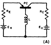
Base-controlled and collector-controlled relaxation oscillators are illustrated in Figs. 6-18 (A) and 6-18 (B). Both operate very much like the emitter-controlled type, and are analyzed on the basis of their respective operating characteristics, illustrated in Fig. 6-9 (A) and (C). The main difference is that the base-controlled type uses an inductance for the storage and release of circuit energy.
While the R-C time constant of the collector- and emitter-controlled relaxation oscillator is fixed by the required operating frequency, the C to R ratio should be as high as possible. This causes minimum degeneration in the circuit, and, at the same time, increases the surge current handling capacity of the condenser. As before, the value of the base resistor RB is determined by the amount of positive feedback required for sustained operation.
|
||||
Home  Transistor Oscillators Transistor Oscillators  Relaxation Oscillators Relaxation Oscillators  Base- and Collector- Controlled Oscillators Base- and Collector- Controlled Oscillators |
||||
Last Update: 2010-11-17


