| Transistor Basics is a free introductory textbook on transistors and their basic applications. See the editorial for more information.... |

|

Home  Transistor Oscillators Transistor Oscillators  Relaxation Oscillators Relaxation Oscillators  Synchronized Relaxation Oscillator Synchronized Relaxation Oscillator |
||


|
||
|
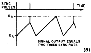
Synchronized Relaxation OscillatorAuthor: Leonard Krugman The operation of a synchronized relaxation oscillator is easily understood in view of the fundamentals of operation covered in the preceding paragraphs. The basic circuit is the same, but the relaxation frequency is made slightly less than the synchronizing frequency. Referring to Fig. 6-17 (B), assume that operation is moving from point A toward point B, and that a positive pulse, large enough to instantly move operation to point B, is applied to the emitter. The effect, as illustrated in Fig. 6-20 (A), is the same as decreasing the time constant RECE, and the relaxation frequency becomes the same as that of the applied synchronizing pulse. The actual point at which the synchronizing signal arrives is not critical as long as the pulse amplitude is large enough to carry the operation into the negative-resistance region. Notice, however, that the magnitude of the sawtooth voltage is reduced by an amount equal to that of the pulse. The dotted line represents the voltage waveform without synchronization.
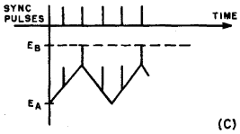
Fig. 6-20. Synchronized controlled (A) waveform, (B) frequency multiplication waveforms, (C) frequency divider waveforms.
Figure 6-20 (C) illustrates the application of the synchronized relaxation oscillator as a frequency divider. In this example, the input frequency is three times that of the relaxation rate. As long as the synchronizing rate is an integral multiple of the basic frequency, the oscillator remains under control. Theoretically, any division ratio is possible, but in practical circuits the ratio is limited by the non-linearity of the sawtooth wave near the critical voltage EB. Consistent operation for division ratios up to approximately 10 to 1 can be easily attained. Ratios higher than these require critical design for reliable operation. Negative synchronizing pulses can be used to operate the base or collector-controlled oscillator types. The many ramifications of the basic relaxation oscillator are too numerous to cover, but the experimenter may find many useful applications for this circuit. If, for example, time constants are inserted in both the emitter and collector circuits, the relaxation oscillator can be synchronized by a pulse applied to either electrode. The circuit may also be biased in either the saturation or cut-off region, so that it remains non-oscillatory until pushed into the regenerative region by an external pulse. The last type falls under the general category of trigger circuits.
|
||
Home  Transistor Oscillators Transistor Oscillators  Relaxation Oscillators Relaxation Oscillators  Synchronized Relaxation Oscillator Synchronized Relaxation Oscillator |
||
Last Update: 2010-11-17


