| Transistor Basics is a free introductory textbook on transistors and their basic applications. See the editorial for more information.... |

|

Home  Transistor Oscillators Transistor Oscillators  Trigger Circuits Trigger Circuits  Bistable Operation Bistable Operation |
||


|
||
|
Bistable OperationAuthor: Leonard Krugman
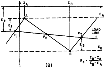
Fig. 6-22. (A) Basic bistable trigger circuit. (B) Idealized characteristics.
The value of RE is selected to provide the three necessary operating points. It is not critical and may vary considerably but, in general, it should be fairly low. Notice that the potential of the emitter battery Ee fixes the location of P1, which in turn determines the required value of the trigger pulse E1 A low battery voltage, then, causes sensitive operation, since the triggering can be accomplished with a small pulse. A large value of Ee results in less sensitive but more reliable operation, since the circuit is less likely to be triggered by noise or other unwanted circuit disturbances. The final choice of both Ee and RE should be based on the most sensitive combination providing reliability.
|
||
Home  Transistor Oscillators Transistor Oscillators  Trigger Circuits Trigger Circuits  Bistable Operation Bistable Operation |
||
Last Update: 2010-11-17


