| Transistor Basics is a free introductory textbook on transistors and their basic applications. See the editorial for more information.... |

|

Home  Transistor High Frequency Applications Transistor High Frequency Applications  High Frequencies Circuits High Frequencies Circuits  I-F Amplifiers I-F Amplifiers |
||


|
||
|
I-F AmplifiersAuthor: Leonard Krugman In general, the upper frequency limit of the junction transistor is considerably lower than the limits of the point-contact type. On the other hand, the junction type has a lower noise factor, and better stability in some applications. These factors frequently make it advantageous to use the junction transistor in some high frequency applications even if an additional stage or two may be required.
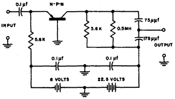
Fig. 7-4. Typical transistor i-f amplifier. Figure 7-4 illustrates one stable form of i-f amplifier stage using a WE 1752 N-P-N transistor. The operating frequency is 455 kc, and the gain is 18 db.
The cascading of transistor i-f is more complicated than that of vacuum tubes. The main contributing factors are the effect of the output load on the input impedance, and the effect of the generator impedance on the output impedance. These factors show up largely in the design of interstage coupling networks.
|
||
Home  Transistor High Frequency Applications Transistor High Frequency Applications  High Frequencies Circuits High Frequencies Circuits  I-F Amplifiers I-F Amplifiers |
||
Last Update: 2010-11-17


