| Wireles Networking is a practical guide to planning and building low-cost telecommunications infrastructure. See the editorial for more information.... |

|
Home  Antennas and Transmission Lines Waveguides Antennas and Transmission Lines Waveguides |
||||||||||||||||||||||||||||||||||||||||


|
  |
|||||||||||||||||||||||||||||||||||||||
|
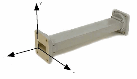
WaveguidesAbove 2 GHz, the wavelength is short enough to allow practical, efficient energy transfer by different means. A waveguide is a conducting tube through which energy is transmitted in the form of electromagnetic waves. The tube acts as a boundary that confines the waves in the enclosed space. The skin effect prevents any electromagnetic effects from being evident outside the guide. The electromagnetic fields are propagated through the waveguide by means of reflections against its inner walls, which are considered perfect conductors. The intensity of the fields is greatest at the center along the X dimension, and must diminish to zero at the end walls because the existence of any field parallel to the walls at the surface would cause an infinite current to flow in a perfect conductor. Waveguides, of course, cannot carry RF in this fashion. The X, Y and Z dimensions of a rectangular waveguide can be seen in the following figure:
There are an infinite number of ways in which the electric and magnetic fields can arrange themselves in a waveguide for frequencies above the low cutoff frequency. Each of these field configurations is called a mode. The modes may be separated into two general groups. One group, designated TM (Transverse Magnetic), has the magnetic field entirely transverse to the direction of propagation, but has a component of the electric field in the direction of propagation. The other type, designated TE (Transverse Electric) has the electric field entirely transverse, but has a component of magnetic field in the direction of propagation. The mode of propagation is identified by the group letters followed by two subscript numerals. For example, TE 10, TM 11, etc. The number of possible modes increases with the frequency for a given size of guide, and there is only one possible mode, called the dominant mode, for the lowest frequency that can be transmitted. In a rectangular guide, the critical dimension is X. This dimension must be more than 0.5 λ at the lowest frequency to be transmitted. In practice, the Y dimension usually is made about equal to 0.5 X to avoid the possibility of operation in other than the dominant mode. Cross-sectional shapes other than the rectangle can be used, the most important being the circular pipe. Much the same considerations apply as in the rectangular case. Wavelength dimensions for rectangular and circular guides are given in the following table, where X is the width of a rectangular guide and r is the radius of a circular guide. All figures apply to the dominant mode.
Energy may be introduced into or extracted from a waveguide by means of either an electric or magnetic field. The energy transfer typically happens through a coaxial line. Two possible methods for coupling to a coaxial line are using the inner conductor of the coaxial line, or through a loop. A probe which is simply a short extension of the inner conductor of the coaxial line can be oriented so that it is parallel to the electric lines of force. A loop can be arranged so that it encloses some of the magnetic lines of force. The point at which maximum coupling is obtained depends upon the mode of propagation in the guide or cavity. Coupling is maximum when the coupling device is in the most intense field. If a waveguide is left open at one end, it will radiate energy (that is, it can be used as an antenna rather than as a transmission line). This radiation can be enhanced by flaring the waveguide to form a pyramidal horn antenna. We will see an example of a practical waveguide antenna for WiFi later in this chapter.
Here is a table contrasting the sizes of various common transmission lines. Choose the best cable you can afford with the lowest possible attenuation at the frequency you intend to use for your wireless link.
|
||||||||||||||||||||||||||||||||||||||||
| Home Antennas and Transmission Lines Waveguides |
|
|||||||||||||||||||||||||||||||||||||||
Last Update: 2010-12-02