| Wireles Networking is a practical guide to planning and building low-cost telecommunications infrastructure. See the editorial for more information.... |

|
Home  Antennas and Transmission Lines Antennas Radiation Pattern Antennas and Transmission Lines Antennas Radiation Pattern |
||||||||||


|
  |
|||||||||
|
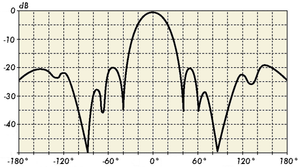
Radiation PatternThe radiation pattern or antenna pattern describes the relative strength of the radiated field in various directions from the antenna, at a constant distance. The radiation pattern is a reception pattern as well, since it also describes the receiving properties of the antenna. The radiation pattern is three-dimensional, but usually the measured radiation patterns are a two-dimensional slice of the three-dimensional pattern, in the horizontal or vertical planes. These pattern measurements are presented in either a rectangular or a polar format. The following figure shows a rectangular plot presentation of a typical ten-element Yagi. The detail is good but it is difficult to visualize the antenna behavior in different directions.
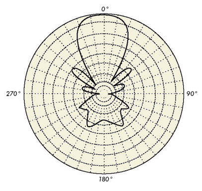
Polar coordinate systems are used almost universally. In the polar-coordinate graph, points are located by projection along a rotating axis (radius) to an intersection with one of several concentric circles. The following is a polar plot of the same 10 element Yagi antenna.
Polar coordinate systems may be divided generally in two classes: linear and logarithmic. In the linear coordinate system, the concentric circles are equally spaced, and are graduated. Such a grid may be used to prepare a linear plot of the power contained in the signal. For ease of comparison, the equally spaced concentric circles may be replaced with appropriately placed circles representing the decibel response, referenced to 0 dB at the outer edge of the plot. In this kind of plot the minor lobes are suppressed. Lobes with peaks more than 15 dB or so below the main lobe disappear because of their small size. This grid enhances plots in which the antenna has a high directivity and small minor lobes. The voltage of the signal, rather than the power, can also be plotted on a linear coordinate system. In this case, too, the directivity is enhanced and the minor lobes suppressed, but not in the same degree as in the linear power grid.
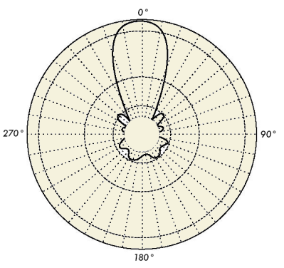
In the logarithmic polar coordinate system the concentric grid lines are spaced periodically according to the logarithm of the voltage in the signal. Different values may be used for the logarithmic constant of periodicity, and this choice will have an effect on the appearance of the plotted patterns. Generally the 0 dB reference for the outer edge of the chart is used. With this type of grid, lobes that are 30 or 40 dB below the main lobe are still distinguishable. The spacing between points at 0 dB and at -3 dB is greater than the spacing between -20 dB and -23 dB, which is greater than the spacing between -50 dB and -53 dB. The spacing thus correspond to the relative significance of such changes in antenna performance. A modified logarithmic scale emphasizes the shape of the major beam while compressing very low-level (>30 dB) sidelobes towards the center of the pattern.'
There are two kinds of radiation pattern: absolute and relative. Absolute radiation patterns are presented in absolute units of field strength or power. Relative radiation patterns are referenced in relative units of field strength or power. Most radiation pattern measurements are relative to the isotropic antenna, and the gain transfer method is then used to establish the absolute gain of the antenna. The radiation pattern in the region close to the antenna is not the same as the pattern at large distances. The term near-field refers to the field pattern that exists close to the antenna, while the term far-field refers to the field pattern at large distances. The far-field is also called the radiation field, and is what is most commonly of interest. Ordinarily, it is the radiated power that is of interest, and so antenna patterns are usually measured in the far-field region. For pattern measurement it is important to choose a distance sufficiently large to be in the far-field, well out of the near-field. The minimum permissible distance depends on the dimensions of the antenna in relation to the wavelength. The accepted formula for this distance is: rmin = 2d2/λ where rmin is the minimum distance from the antenna, d is the largest dimension of the antenna, and λ is the wavelength.
|
||||||||||
| Home Antennas and Transmission Lines Antennas Radiation Pattern |
|
|||||||||
Last Update: 2010-12-02