| Wireles Networking is a practical guide to planning and building low-cost telecommunications infrastructure. See the editorial for more information.... |

|
Home  Antennas and Transmission Lines Antennas Polarization Antennas and Transmission Lines Antennas Polarization |
|||


|
  |
||
|
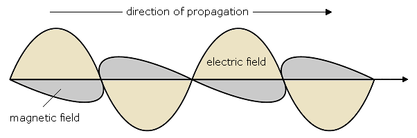
PolarizationPolarization is defined as the orientation of the electric field of an electromagnetic wave. Polarization is in general described by an ellipse. Two special cases of elliptical polarization are linear polarization and circular polarization. The initial polarization of a radio wave is determined by the antenna. With linear polarization, the electric field vector stays in the same plane all the time. The electric field may leave the antenna in a vertical orientation, a horizontal orientation, or at some angle between the two. Vertically polarized radiation is somewhat less affected by reflections over the transmission path. Omnidirectional antennas always have vertical polarization. With horizontal polarization,such reflections cause variations in received signal strength. Horizontal antennas are less likely to pick up man-made interference, which ordinarily is vertically polarized.
Polarization MismatchIn order to transfer maximum power between a transmit and a receive antenna, both antennas must have the same spatial orientation, the same polarization sense, and the same axial ratio. When the antennas are not aligned or do not have the same polarization, there will be a reduction in power transfer between the two antennas. This reduction in power transfer will reduce the overall system efficiency and performance. When the transmit and receive antennas are both linearly polarized, physical antenna misalignment will result in a polarization mismatch loss, which can be determined using the following formula: Loss (dB) = 20 log (cos φ) ...where φ is the difference in alignment angle between the two antennas. For 15° the loss is approximately 0.3 dB, for 30° we lose 1.25 dB, for 45° we lose 3 dB and for 90° we have an infinite loss. In short, the greater the mismatch in polarization between a transmitting and receiving antenna, the greater the apparent loss. In the real world, a 90° mismatch in polarization is quite large but not infinite. Some antennas, such as yagis or can antennas, can be simply rotated 90° to match the polarization of the other end of the link. You can use the polarization effect to your advantage on a point-to-point link. Use a monitoring tool to observe interference from adjacent networks, and rotate one antenna until you see the lowest received signal. Then bring your link online and orient the other end to match polarization. This technique can sometimes be used to build stable links, even in noisy radio environments.
|
|||
| Home Antennas and Transmission Lines Antennas Polarization |
|
||
Last Update: 2010-12-02