| Electrical Communication is a free textbook on the basics of communication technology. See the editorial for more information.... |

|
Home  Transmission Lines Input Impedance of Any Line with Any Termination Transmission Lines Input Impedance of Any Line with Any Termination |
|||


|
  |
||
Input Impedance of Any Line with Any TerminationAs explained in the section Characteristic Impedance, the input impedance of a line terminated in its characteristic impedance Z0 equals its characteristic impedance Z0. Telephone lines are usually terminated in impedances closely approximating their characteristic impedances so that the maximum signal energy will be extracted from the oncoming wave and little reflection will occur. Sometimes it is desirable to terminate transmission lines in impedances other than their characteristic impedances, and, if this is done, the input, or driving-point, impedance, will not equal the terminating impedance. If a line is terminated with some impedance Zr that does not equal Z0, then an impedance mismatch exists, all the energy in the wave is not absorbed, and a wave is reflected back toward the sending end.
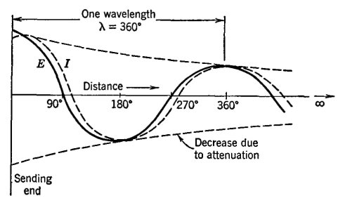
The wave that arrives back at the sending end combines with the wave entering the line from the signal source (generator) connected at the sending end. The exact manner of combining depends on the phase relations between the two components. The input impedance when the line termination is not Z0 will equal the sending-end voltage Es divided by the sending-end current IS. The sending-end voltage Es will be the resultant of an initial voltage wave entering the line and a reflected voltage wave arriving back from the mismatched impedance Zr. The sending-current Is will be the resultant of an initial current wave and a reflected current wave. In deriving the equation for the input impedance of a line terminated in any impedance Zr, instead of its characteristic impedance Z0, it is assumed first that the line is terminated in Z0, and hence the magnitudes of the initial voltage and current waves can be found. The portions of these waves that reach the receiving end are determined by the length of line and the attenuation constant. The magnitudes and the phase relations of the reflected components depend on the magnitude and the angle of the terminating impedance Zr. Also, the magnitudes and phase relations of the reflected components that arrive back at the sending end and combine with the initial components to determine Es and Is depend on the propagation constant and the length of line.6,8 The equation for the input impedance of a line with any termination Zr can be found from equations 23 and 24. The line under consideration is assumed to be l miles in length, to have a propagation constant of γ = sqrt(zy) per mile, and to have a characteristic impedance of Z0 = sqrt(z/y). Then, from equation 23 the sending-end voltage Es will be
and from equation 24 the sending-end current will be
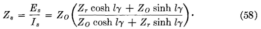
The voltage Er at the receiving end is Er = IrZr, and, when this is substituted in equations 56 and 57, and when equation 56 is divided by equation 57 to obtain the input impedance,
All terms in this equation are complex numbers, and the input, or driving-point, impedance Zs measured at the sending end also is a complex number.
|
|||
| Home Transmission Lines Input Impedance of Any Line with Any Termination |
|
||


Last Update: 2011-05-30