| Electrical Communication is a free textbook on the basics of communication technology. See the editorial for more information.... |
|
Home  Transmission Lines Input Impedance of Open and Shorted Lossless Lines Transmission Lines Input Impedance of Open and Shorted Lossless Lines |
|||||||


|
  |
||||||
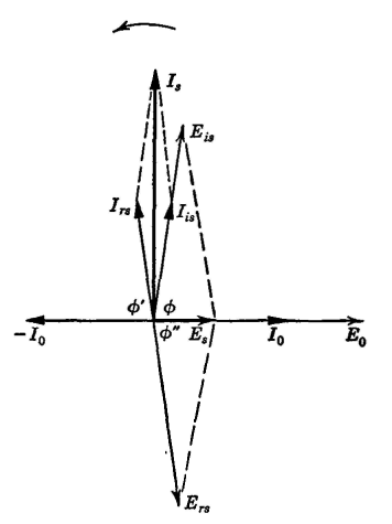
Input Impedance of Open and Shorted Lossless LinesSuch lines cannot absorb power, and hence their input impedances must be either pure inductive reactance, pure capacitive reactance, or they must be zero or infinity. These statements can be proved by applying equations 61 and 65 to lossless lines of various lengths and can be demonstrated vectorially as in Fig. 10. Open-Circuited Line Less than λ/4 in Length. It is assumed that the line is lossless and that the characteristic impedance is pure resistance. The voltage E0 and the current I0 at the open-circuited receiving end are in phase. These have been taken as a convenient base in Fig. 10. The initial voltage wave Eis and the initial current wave Iis at the sending end will be displaced φ degress (less than 90° for the line under consideration) as shown. At the distant open end the current component is reflected with a change in phase of 180° and then travels toward the sending end, becoming Irs. The angles φ and φ' are equal because as much time is required to travel in one direction as the other. The voltage component is reflected without a change in phase, and the reflected component Ers at the sending end has the position shown. Of course φ" and φ are equal. The voltage at the sending end is composed of two voltages, the initial component Eis is just entering the line, and the reflected component Ers is just arriving back from the distant open end. The actual sending-end voltage will accordingly be the vector sum of Eis and Ers and becomes Es of Fig. 10. Two current components exist at the sending end, the initial component Iis is just entering the line, and Irs is just arriving back from the distant open end. The resultant current Is at the sending end is the vector sum of these two components. Thus, the sending-end voltage Es and the sending-end current Is for a lossless line less than 1/4λ. in length are 90° out of phase, with the current leading the voltage. The input impedance is, therefore, a value of pure capacitive reactance, and the line is equivalent to a capacitor. The numerical value of the reactance or the capacitance can be determined by equation 58 or by equation 61 discussed on page 206. Open-Circuited Line Greater than λ/4 in Length. If an open-circuited lossless line has a length greater than λ/4, but less than λ/2, Fig. 10 can be extended to cover the conditions. Vectors Eis and Iis will lead vectors E0 and I0 by an angle φ greater than 90° because the line length is greater than λ/4. Also, vector Irs lags vector -I0 by an angle φ' that is greater than 90°. Furthermore, angle φ" exceeds 90°. If these changes are made on Fig. 10, Eis will be in the second quadrant, Ers will be in the third quadrant, and the resultant voltage Es will be opposite in direction to that shown in Fig. 10. Vector Is will be in the same position, and hence the sending-end voltage Es will lead the sending-end current Is by 90°. The input impedance is, therefore, a value of pure inductive reactance, and the line is equivalent to an inductor. The numerical value of the reactance or the inductance can be determined by equation 58 or by equation 61 on page 206.
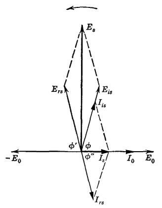
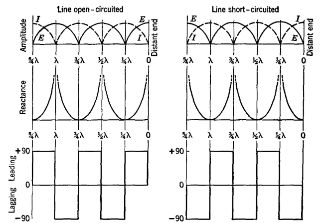
Short-Circuited Line Less than λ/4 in Length, A vector diagram for this line is shown in Fig. 11. Vectors E0,I0, Eis and Iis are located as previously explained. But, since the line is short circuited, the voltage component is reversed at reflection as shown by -E0. The reflected component at the sending end is Ers, and lags -E0 by the angle φ', and the sending-end voltage is the resultant, Es. The reflected current component at the sending end is Irs and lags I0 by the angle φ". The sending-end current is the resultant IS, which lags the sending-end voltage Es by 90°. The input impedance is, therefore, a value of pure inductive reactance, and the line is equivalent to an inductor. The numerical value of the reactance or the inductance can be determined by equation 58 or by equation 65 on page 207. Short-Circuited Line Greater than λ/4 in Length. If a short-circuited lossless line has a length greater than λ/4, but less than λ/2, Fig. 11 can be extended to give the input-impedance relations. The angles are greater than 90°, and because of this the resultant sending-end current vector will be opposite in direction from that of Fig. 11 and the resultant sending-end voltage vector will remain in the position shown. Thus, the current leads the voltage by 90°, the input impedance is a value of pure capacitive reactance, and the line is equivalent to a capacitor. The numerical value of the reactance or the capacitance can be determined by equation 58 or by equation 65 on page 207. The relationships discussed in this section are summarized in Fig. 12. In studying these diagrams, line lengths should be measured from the distant end. For instance, an open-circuited line f A in length would have a value of reactance that was "low," and the angle would be lagging, indicating inductive reactance.
Open-circuited and short-circuited lossless lines often are called resonant lines because their input impedances vary between zero and infinity (Fig. 12). Such lines are extensively used to simulate (Fig. 13) capacitors, inductors, series resonant circuits, and parallel resonant circuits.
|
|||||||
| Home Transmission Lines Input Impedance of Open and Shorted Lossless Lines |
|
||||||
Last Update: 2011-05-30