| Electrical Communication is a free textbook on the basics of communication technology. See the editorial for more information.... |

|
Home  Transmission Lines Constants of Open-Wire Lines at Low Frequencies Transmission Lines Constants of Open-Wire Lines at Low Frequencies |
|||||||||||||||||||||||||||||||||||||||||||||||||||||||||||||||||||||||||||||||||||||||||||||||||||||||||||||||||||||||||||||||||||||||||||||||||||||||||||||||||||||||||||||||||||||||||||||||||||||||||||


|
  |
||||||||||||||||||||||||||||||||||||||||||||||||||||||||||||||||||||||||||||||||||||||||||||||||||||||||||||||||||||||||||||||||||||||||||||||||||||||||||||||||||||||||||||||||||||||||||||||||||||||||||
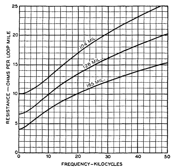
Constants of Open-Wire Lines at Low FrequenciesThe linear electrical constants of a transmission line were discussed on page 193. In this section the numerical values of these will be considered for frequencies particularly from about zero to 50,000 cycles. Open-wire telephone lines are usually made of hard-drawn copper wire of three standard sizes.9 Series Resistance R. Series resistance R is the effective series resistance and is composed of the direct-current resistance and the additional resistance effect caused by skin effect. Theoretically, a proximity effect also exists, but in open-wire lines this has negligible effect on the resistance. This proximity effect is caused by the presence of the other closely parallel wires. The alternating, or effective, resistance of standard telephone lines is shown in Fig. 14. The increase in resistance caused by skin effect is usually determined from curves10 such as Fig. 15. The effective resistance Rac is related to the direct resistance Rdc by the equation
where σ has the value given by Fig. 15. For this figure, the value of x for copper wires is given by the relation
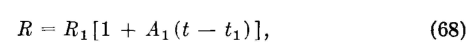
where d is the wire diameter in mils, and f is the frequency in megacycles. Both the contact resistance in wire joints and the actual decrease in the size of the wire due to corrosion tend to make the measured resistance of old wires greater than that given by Fig. 14. For the hard-drawn copper used in communication circuits, the effective resistance of the wire varies with temperature according to
the relation9
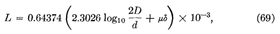
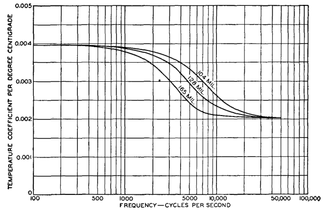
where R is the effective resistance at temperature t, R1 is the resistance at temperature t1, and A1 is the alternating-current temperature coefficient of resistance at temperature t1 and can be obtained from Fig. 16. Temperatures are in degrees centigrade. Series Inductance L, The series self-inductance of an open-wire transmission line of two parallel wires is9
where L is in henrys per loop mile, d is the diameter of each wire, and D is the distance between centers both in the same units, μ is the permeability of the wire, and δ is a factor depending on frequency.11 For hard-drawn copper wires, the permeability is unity, and for audio frequencies9 μδ = 0.25. Equation 69 applies with best accuracy when
the ratio D/d is at least 10. The inductance of telephone lines at various frequencies is given in Table I. Shunt Capacitance C. The shunt capacitance of an open-wire transmission line of two parallel wires is9
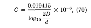
where C is in farads per loop mile (mile of line), d is the diameter, and D is the distance between centers both in the same units. This equation applies with greatest accuracy when the ratio D/d is greater than about 10. Values for the capacitance between wires of different sizes and of different spacings are given in Table II. Since on an actual line the
TABLE I INDUCTANCE OF OPEN-WIRE LINES (From reference 9.)
capacitance depends to some extent on the presence of other wires,9 values are given for wires isolated in space, and also for wires on a 40-wire line. The effect of frequency is negligible. TABLE II CAPACITANCE VALUES FOR OPEN-WIRE LINES (From reference 9.)
Shunt Conductance G. This is the most erratic of the line constants.9 Shunt conductance is not the direct-current conductance between wires but is of the nature explained9 in the following quotation: The determination of the value of G for direct current is quite simple, involving merely a measurement of the actual conductance between wires for a length of circuit short enough to avoid propagation effects. For alternating currents, however, it is customary to employ an equivalent value of G which includes all the losses suffered by the power transmitted over the pair except the normal I2R loss in the wires themselves. This inclusion of numerous little-understood losses in the general term leakage has at times served to insulate the individual losses from analysis.* There are many paths by which the leakage currents can reach the other wire of a pair, or ground. Leakage occurs through the air itself but is of little importance. It occurs through trees or other foreign objects touching the wires. It also occurs at insulators. Insulator leakages are discussed in a paper12 from which the following is summarized.
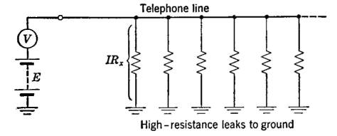
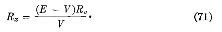
Current leakage at insulators may be resolved into two components, one in phase with the potential and one leading the potential by 90°, This in-phase component represents an energy loss and is the more important component. The term shunt conductance refers to the conductance corresponding to the in-phase component. Both the in-phase and reactive components in flowing through the resistance of the line conductors produce energy losses, but these are negligible. All other energy losses that occur because of the insulators, whether they actually occur at the insulators or elsewhere, are attributed to the insulators. Shunt conductance varies greatly with weather conditions, the age of the insulators and the line, and similar factors. It is extremely difficult to maintain proper insulation on lines close to the sea or to salt lakes,13 or in certain regions subject to alkali dust storms. Methods of measuring the shunt conductance G are discussed in reference 14. Values are given in Table IV. Lines are quite often given direct-current tests to determine their direct-current insulation resistance. Such tests are often made with a voltmeter as indicated in Fig. 17. A voltmeter having a resistance of * Reprinted by permission, courtesy Bell System Technical Journal. about 100,000 ohms is satisfactory. The IRX drop across the insulation resistance of the entire line equals the battery voltage E minus the reading V of the voltmeter, or IRX = E - V, and Bx = (E - V)/I. The voltmeter and the equivalent resistance of the line are in series, and thus the current through each is the same. The current through the voltmeter (and Rx) is I = V/RV, and thus it can be written that
|
|||||||||||||||||||||||||||||||||||||||||||||||||||||||||||||||||||||||||||||||||||||||||||||||||||||||||||||||||||||||||||||||||||||||||||||||||||||||||||||||||||||||||||||||||||||||||||||||||||||||||||
| Home Transmission Lines Constants of Open-Wire Lines at Low Frequencies |
|
||||||||||||||||||||||||||||||||||||||||||||||||||||||||||||||||||||||||||||||||||||||||||||||||||||||||||||||||||||||||||||||||||||||||||||||||||||||||||||||||||||||||||||||||||||||||||||||||||||||||||


Last Update: 2011-06-06