| Electrical Communication is a free textbook on the basics of communication technology. See the editorial for more information.... |
|
Home  Telephone Toll Service and Systems Type C Carrier Telephone Systems Telephone Toll Service and Systems Type C Carrier Telephone Systems |
|||||||||||||
| See also: Analysis of an Amplitude-Modulated Wave | |||||||||||||


|
  |
||||||||||||
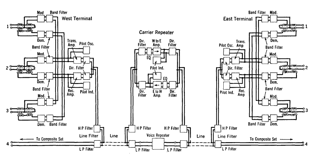
Type C Carrier Telephone SystemsThe type C system was first installed about 1925 and has been very extensively used. It incorporates the most desirable features of the systems just considered. Like the type A system, the carrier is suppressed, and hence the effect of line attenuation is minimized. Like the type B, different frequencies are used for transmitting and receiving, and filters, instead of carrier-frequency hybrid coils, are used to separate the talking and the receiving signals. The original type C carrier telephone system was extensively modified about 1938 to take advantage of developments in communication. Original Type C Carrier Telephone System.30 The schematic diagram of the original type C carrier is shown in Fig. 20. To explain the operation of this system, assume that a person whose telephone is connected to channel 1 at the left is speaking to a person whose telephone is connected to channel 1 at the right. The incoming speech signals pass through the voice-frequency hybrid coil, and to the modulator at the top. This is a balanced modulator (page 421) that eliminates the carrier but produces both sidebands. The band filter selects one sideband and rejects the other. The selected sideband passes down to the common wires leading to the transmitting amplifier, where all the incoming signals to be transmitted are amplified to the proper level for impressing on the line. The amplified signals from the three channels pass through the high-pass filter and hence to the line. Each of the three modulators is fed with a different carrier frequency, and hence each of the three sidebands that are transmitted simultaneously is at a different frequency as Fig. 18 shows.
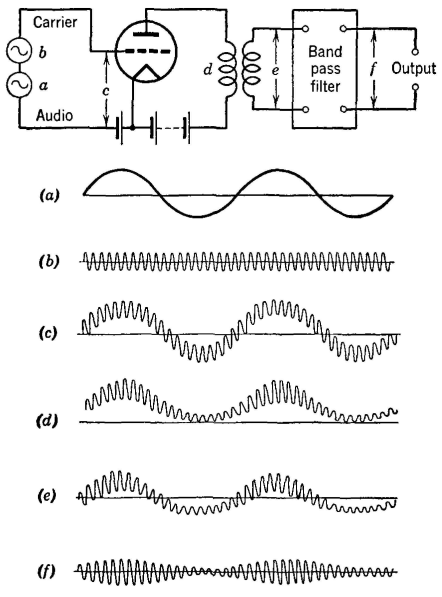
At a repeater point the carrier frequencies are separated from the voice frequencies by the high-pass and low-pass filters. At the carrier amplifier the transmitting and the receiving signals are separated by directional filters. The equalizer functions as explained on page 410 The sideband signals of the three channels are amplified in the "west to east" amplifier,30 pass through the directional filter, the high-pass filter, and the amplified signals are then impressed on the line toward the "east terminal" at the right of Fig. 20. At the east terminal the received sidebands from the transmitting "west terminal" are passed by the high-pass line filter upward to the directional filters. Since the east terminal now is being considered as receiving from the west terminal, the three incoming sidebands will pass through the lower directional filter and to the common circuit leading to the demodulating apparatus. The sideband from channel 1 will be passed by the band-pass filter of channel 1 to the demodulator (page 421). The output of the demodulator will contain the original message at audio frequencies, and this is passed by the voice-frequency hybrid coil to the telephone set of the listener. Channels 2 and 3 function in a manner similar to that just explained. The pilot channel noted on Fig. 20 is for monitoring and adjusting the transmission to ensure that the signal strength is correct at all times.30 Modulation in the Original Type C Systems.30 As discussed in the preceding paragraphs, sidebands, which contain the information to be transmitted, are created in the modulator. A modulator is defined1 as "a device to effect the process of modulation. It may be operated by virtue of some non-linear characteristic, or by a controlled variation of some circuit quantity." In the original type C carrier system the non-linear relation between grid voltage and plate current in triode thermionic vacuum tubes was used to produce modulation. To accomplish this, the speech signals to be transmitted and the carrier frequency are impressed simultaneously on the grids of tubes so biased that operation is on the non-linear portion of the characteristic curves as shown in Fig. 21. As will be explained, the sidebands are created in the process of distortion. This statement has been italicized because sometimes it is thought that merely "mixing" two waves, or "beating" two waves, creates sidebands. This is not true: the sidebands are created by simultaneously distorting the two waves, and the modulating tubes must be operated so that they distort, and not merely amplify, if the sidebands are to be created.
If a single tube is operated so that it distorts as shown in Fig. 21, the shapes of the resulting waves will be as shown in Fig. 22. As indicated, the final signal is a modulated wave containing the carrier and two sidebands as explained on page 413.
Over the curved portion used in modulation as shown in Fig. 21, the equation for the plate current is approximately
In this equation a and b are constants, and eg is the instantaneous grid voltage. When the instantaneous input carrier voltage wave is Ecsinωct and when the instantaneous modulating voltage wave is Evsinωvt, then
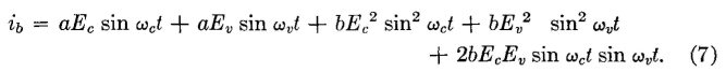
When this expression is substituted in equation 5, the instantaneous plate current becomes
From trigonometry,
Also,
If these substitutions are made, equation 7 becomes
When the indicated multiplications are performed and all constant terms dropped (since the alternating portions only are of primary interest), equation 8 may be written
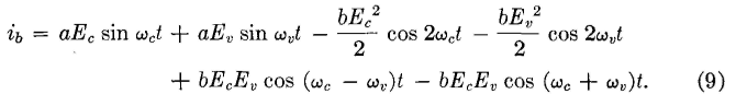
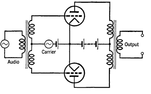
Thus, remembering that fc = ωc/2π represents the carrier frequency, and that fv=ωv/2π represents the voice frequency, the following alternating components exist in the modulator output: 1. ft (the voice frequency, represented by the second term). 2. 2fc (twice the carrier frequency, represented by the third term). 3. 2fv (twice the voice frequency, represented by the fourth term), 4. fc (the carrier frequency, represented by the first term). 5. fc - fv (the lower sideband, represented by the fifth term). 6. fc + fv (the upper sideband, represented by the last term). If the first three components are eliminated (with the filters), then the resulting wave will have the shape of Fig. 22(f) and will have the characteristics discussed on page 414. In the type C carrier system the carrier and one sideband are suppressed. The carrier is suppressed in the push-pull balanced modulator of Fig. 23. In this circuit the carrier voltage drives the two grids in phase, but the voice-frequency signal voltage drives the two grids 180° out of phase. The unwanted sideband is suppressed by the band-pass filter associated with each modulator in Fig. 20.
The statements made regarding cancellation of the carrier can be proved as follows: Let the instantaneous carrier voltage be expressed as before, Ecsinωct. Let the instantaneous voice-frequency modulating voltage be +Evsinωvt for one tube, and-Evsinωvt for the other tube. Expansions are then made for the plate current of each tube as previously explained for one tube, and the expressions are subtracted, because each current flows through one half of the primary in a direction opposite to that of the other. Demodulation in Original Type C Carrier Systems30 Demodulation is defined1 as "the process whereby a wave resulting from modulation is so operated upon that a wave is obtained having substantially the characteristics of the original modulating wave." The demodulating circuit of the original type C carrier system is essentially the circuit of Fig. 23 used for modulation. Because the carrier frequency is not transmitted, it must be supplied by an oscillator associated with the demodulator. Studies similar to those made for modulation will show that, if the received sideband and the locally generated carrier are impressed on the circuit (Fig. 22), a difference frequency will be created. This is the desired voice-frequency signal wave, having the characteristics of the original modulating wave and containing the information that has been transmitted. Modulation and demodulation are the same fundamental processes of distortion by virtue of which the desired new signals (sidebands) are created. In modulation, the information contained in the voice-frequency wave is translated (or moved) to a new and higher frequency band (the sidebands) for transmission. In demodulation, the information contained in the received sideband is translated back to the original voice-frequency band to operate the telephone receiver of the listener. Thus, if the received sideband extends from 6500 to 9800 cycles and the locally generated carrier is 10,000 cycles, the fc - fv term (page 420) will be an audible speech signal occupying a band of frequencies from 200 to 3500 cycles. Improved Type C Carrier Telephone System31,32,33 In about 1938 an improved type C system was developed. The improved system incorporated changes that were revolutionary, particularly with regard to modulation and demodulation. The improved system provides three talking channels in about the same frequency range (about 6000 to 30,000 cycles) as the original system. It is, however, smaller and cheaper and gives improved transmission performance. Amplifiers31,34 with negative feedback (page 300) are used in the carrier repeaters which are spaced at intervals of 125 to 250 miles on open-wire lines. Regulating circuits adjust for changes in line attenuation.
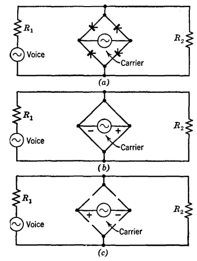
The method of selecting the various sidebands and other details are much as shown in Fig. 20. Modulation in Improved Type C Systems. Copper oxide varistors are used for modulation in the improved system instead of vacuum tubes as in the original system. Many circuit arrangements can be used;35 the one being employed is shown in Fig, 24 (a), and the shapes of the various waves are in Fig. 25. The characteristics of a typical copper oxide varistor are shown in Fig. 43, page 310, and are similar to those shown in Fig. 4, page 274, for the selenium varistor. The numerical values of resistance for varistors of various types are different. In developing the theory of the varistor modulator the assumption is made that the carrier voltage is much larger than the modulating voltage and that the carrier voltage controls the circuit, giving it the characteristics shown in Figs. 24(b) and (c). This is because in the forward or conducting direction the resistance of a varistor unit approaches zero, but in the reverse or nonconducting direction the varistor resistance approaches infinity. Because of these variations, the current flowing through resistor R2, which represents the impedance of the toll line leading to the distant receiving station, is as shown by Fig. 25(c). If this wave is examined critically, it is seen to contain the voice-frequency modulating signal and high-frequency components other than the carrier, because, theoretically, the varistor bridge circuit offers either zero or infinite impedance to the carrier voltage. Among the high-frequency components are upper and lower sidebands. The carrier voltage is assumed to control the switching of Fig. 24 and to have no other effect. The current through R2 can be found by writing the equation for the transfer impedance1 between the source of voice-frequency modulating voltage and R2, and then dividing the transfer impedance into the expression for the modulating voltage. Or the expression for the transfer admittance multiplied by the modulating voltage will give the modulated current through R2.
The transfer admittance has the form of the wave composed of a constant term and alternating terms, because it is either zero as in Fig. 24(b) or 1/(Rl + R2) as in Fig. 24(c). The equation for a rectangular wave was given on page 318. Using this as a basis, and remembering that the transfer admittance is never negative, the equation for the instantaneous value of the transfer admittance becomes the values ωc = 2πfc being used because the transfer admittance is varying at the carrier rate. If the instantaneous modulating voice-frequency signal Evsinωvt is multiplied by the equation for the transfer admittance and if substitutions are made much as on page 420, it will be found that the desired sidebands have been created.
Demodulation in Improved Type C Systems. At the receiving end the carrier frequencies are separated from the voice frequencies on the same line by filters. The sidebands used for receiving are separated by filters from the sidebands used in transmitting. Next, each sideband is selected by band-pass filters for the proper channel. Demodulation is accomplished by a copper oxide varistor-bridge circuit essentially as in modulation. Because the carrier is suppressed at the transmitting end, a wave of the carrier frequency is generated locally and is injected into the demodulator circuit.
|
|||||||||||||
| Home Telephone Toll Service and Systems Type C Carrier Telephone Systems |
|
||||||||||||


Last Update: 2011-06-05