| Electrical Communication is a free textbook on the basics of communication technology. See the editorial for more information.... |

|
Home  Radio Wave Propagation and Antennas Directional Periodic Antennas Radio Wave Propagation and Antennas Directional Periodic Antennas |
|||||||||


|
  |
||||||||
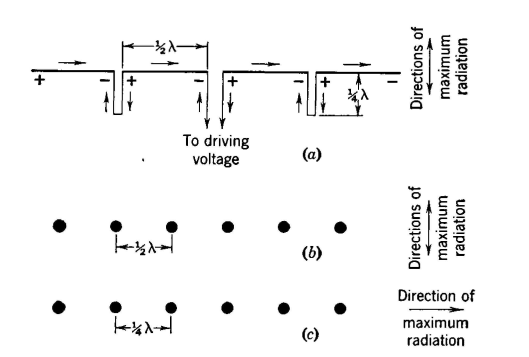
Directional Periodic AntennasIn many radio applications it is desired that the antenna radiating (or receiving) systems be directional. A directional antenna is defined34 as "an antenna having the property of radiating or receiving radio waves more effectively in some directions than others." Directional antennas are particularly useful with important point-to-point installations because they reduce interference, increase secrecy, and save power, resulting in lower overall first costs and operating charges. Directional transmitting antennas are sometimes called directive antennas. Antenna Gain. The gain of an antenna is defined34 as follows: "The measured gain of one transmitting or receiving antenna over another is the ratio of the signal power one produces at the receiver input terminals to that produced by the other, the transmitting power level remaining fixed." The reference antenna for measuring the gain of a directional antenna is often a similar non-directional radiator. The gain as defined is a power gain and is often expressed in decibels. Antenna Arrays. Antenna arrays are systems of antennas coupled together for the purpose of obtaining directional effects.34 When the unit antennas are arranged in a line perpendicular to the direction of transmission the system is called a broadside array, and when the unit antennas are arranged in the direction of transmission it is called an end-on array, end-fire array, or an alignment array.34 Broadside Arrays. One broadside array consists of half-wave antennas arranged along the same straight line and is sometimes called the collinear array. (See also reference 34, linear array.) A simple arrangement is shown in Fig. 20(a). When the driving voltage has the polarity shown, the instantaneous current directions will be as indicated by the arrows. As a result, cancellation occurs for the quarter-wave sections, and the half-wave antennas combine to send signal at right angles to the direction in which they point, giving a free-space radiation pattern similar to Fig. 13(a), but very much more elongated. An array such as Fig. 20 (a) could be horizontal or vertical (or at any other angle) with respect to the earth. Reflection from the earth would affect the radiation pattern. Radiation from the antenna of Fig. 20 (a) will occur in both directions at right angles to the antenna, hence the word "broadside."
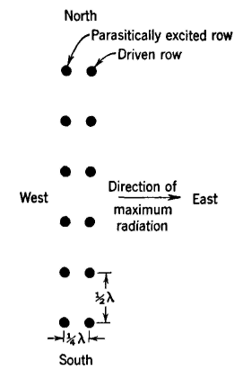
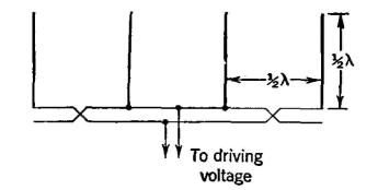
Another broadside array (usually called the broadside array) is shown in Fig. 20(b) in which a number of half-wave antennas are arranged with their axes at right angles to the direction of the array. The dots represent the upper ends of the half-wave antennas. They are λ/2 (or 180°) apart and are driven in phase. The radiation in the plane of the page is zero for the directions in which the radiators are aligned. A signal from one radiator will arrive at a second radiator 180° after it is radiated. By this time, the applied voltage at the second has changed 180°, and the radiation from the second radiator will cancel that which has arrived from the first. Thus cancellation of signal occurs, and there is negligible radiation in the direction of the array. At points in front and in back of the antenna, the radiations add, giving two directions of maximum radiation as shown in Fig. 20(b). This array may be placed at any position with respect to the earth. Its radiation pattern will be affected by reflection from the earth. End-fire, End-on, or Alignment Arrays. This is usually called34 an end-fire array in practice, a typical arrangement being shown in Fig. 20(c). The currents in these radiators (often half-wave dipoles) are equal in magnitude, but the driving arrangement is such that there is a progressive phase lag between adjacent antennas in the direction of maximum radiation. If the radiators are λ/4 apart, the phase lag is 90°, etc. However, the theory does not apply if the spacing exceeds 3A/8. With this arrangement, maximum radiation occurs in the direction of the radiator having the most lagging phase. Reflectors and Directors. It will be noted that the broadside arrays of Fig. 20(a) and (b) radiate equally in both directions, usually a very objectionable feature. They are made to radiate essentially in one direction only by the use of reflectors, directors, or both. An excitery34 is "the portion of a transmitting array, of the type which includes a reflector, which is directly connected with the source of power." A reflector34 is "a parasitic element located in a direction other than the general direction of the major lobe of radiation." A director34 is "a parasitic element located in the general direction of the major lobe of radiation." An antenna array with a reflector is shown in Fig. 21. If a second identical row of conductors is placed λ/4, or 90°, from the driven row of Fig. 20(b), but not connected to it or to the source of radio-frequency energy, then this second row will be parasitically excited by the driven row. A signal leaves a driven exciter of Fig. 21 and arrives at the corresponding reflector 90° after it is radiated. This signal induces a voltage in the reflector which will cause the radiation of a field of 180° out of phase with the exciting field. This field will travel in two directions, one of which is toward the exciter where it arrives 90° after being radiated by the reflector. During this time, the signal voltage driving the exciter has changed 180°, and, hence, the new signal coming from the exciter and the signal from the reflector are in phase and add in the east direction. In the west direction, the original signal and the parasitically radiated signal are 180° out of phase, and radiation largely is cancelled in this direction. Thus radiation occurs largely in the east direction as Fig. 21 indicates. Antennas of this type were formerly used extensively in transoceanic radio-telephone systems, but they have been superseded by rhombic antennas (page 480). A simple arrangement for feeding the driven row of Fig. 21 is shown in Fig. 22.
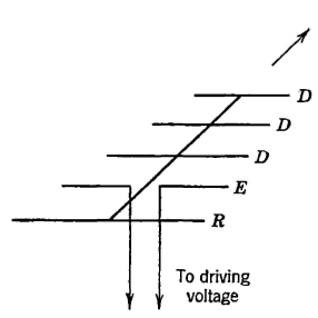
One or more directors (and a reflector as well) are used with the Yagi antenna, named after its inventor. The arrangement of a typical array is shown in Fig. 23; it is often mounted horizontally and arranged for rotation. Spacings of less than 90° are used, and the individual conductors are not all the same length. Some design data are available, but spacings and lengths are usually determined experimentally.37,39 A reflector is usually made longer than the exciter, and the directors are usually made shorter. Only one reflector is usually employed, but sometimes several directors are used.
|
|||||||||
| Home Radio Wave Propagation and Antennas Directional Periodic Antennas |
|
||||||||
Last Update: 2011-05-30